In summary:
- Building a realistic model jet is not about loading the most weapons, but the correct ones.
- Loadouts are dictated by mission profiles, the laws of physics, and the specific historical era.
- Understanding the “why” behind weapon placement and selection transforms a model from a toy into a tactical statement.
- Asymmetrical loadouts are not an error; they are often a reflection of operational reality.
Attention to detail. That is the core of our craft. You spend months perfecting the cockpit, weathering the fuselage, and achieving a flawless canopy. Then comes the final step: ordnance. The temptation is to create a “Christmas tree,” loading every pylon with the biggest, most impressive missiles and bombs in the box. This is a critical error. An aircraft loaded for a photo shoot is not an aircraft loaded for a mission. A nonsensical weapon configuration, no matter how well painted, instantly destroys the realism you have worked so hard to achieve. It signals a fundamental misunderstanding of the subject.
The common advice is to “look at photos,” but this is insufficient. Without context, a photo can be misleading. Was the aircraft on static display? Was it a test configuration? The key is not just to copy what you see, but to understand the doctrine behind it. This guide is not a list of prescribed loadouts. It is a manual of arms. We will dissect the core principles that dictate how a modern fighter is armed: the physics of flight, the timeline of technology, the purpose of the mission, and the subtle art of finishing. By mastering these rules, you will move beyond simply following instructions and begin thinking like an Armament Officer.
This brief will provide the necessary intelligence to ensure your next build is not only visually stunning but tactically sound. We will examine the physical limitations of wing stations, the proper identification of ordnance by era, the meaning behind paint schemes, and the operational logic of asymmetric configurations. We will also cover advanced techniques for achieving maximum realism, from scratch-building parts to strategic aftermarket upgrades. Your mission is to build with intent. Let us begin.
Contents: Avoiding the Impossible Loadout Error
- Why you can’t hang a heavy fuel tank on a wingtip rail?
- Sidewinder B or L: how to match the missile version to the conflict year?
- Blue stripes or Yellow stripes: how to paint missiles for a training diorama?
- Why modern jets often fly with asymmetric loadouts (and why it looks cool)?
- How to simulate the glass lens on the tip of an infrared missile?
- How to Design Simple Model Parts in CAD Without an Engineering Degree?
- Jet Age vs Propellers: Which Era Offers the Best Learning Curve for Weathering?
- Which Aftermarket Upgrade Offers the Best Visual ROI for Your Model Kit?
Why you can’t hang a heavy fuel tank on a wingtip rail?
The most common and jarring error is the misplacement of heavy stores. A wingtip station is not just another hardpoint; it is a point of extreme leverage. The fundamental principle is moment arm effect. The further a weight is from the wing root (the fulcrum), the more rotational force, or torque, it exerts on the wing structure. Hanging a 2,000-pound fuel tank or bomb on a wingtip rail would generate catastrophic stress during flight maneuvers, leading to structural failure. These stations are specifically designed for lightweight, low-drag stores, typically short-range air-to-air missiles like the AIM-9 Sidewinder, which also serve a secondary purpose as wing flutter dampeners.
Furthermore, every aircraft has a defined G-limit, which changes based on its load. A “clean” F-16 might be rated for 9 Gs, but with heavy ordnance on underwing pylons, that limit could be drastically reduced. The aircraft’s flight manual contains extensive charts defining permissible loads for each station and the resulting performance limitations. Ignoring these physical constraints is the fastest way to create a fantasy build. The mission is always constrained by physics. Before hanging any store, you must consider its weight, its distance from the fuselage, and how it impacts the aircraft’s ability to perform its mission.
Actionable Checklist: Wing Station Loading Sanity Check
- Calculate Moment Arm: Multiply the store’s weight by its distance from the wing root. If it’s a heavy store on an outboard pylon, it is likely an incorrect configuration for anything other than a ferry flight with strict G-limits.
- Verify Jettison Clearance: Ensure any jettisoned store, particularly from an inboard pylon, has a clear path to fall away without striking other stores, landing gear, or the tail surfaces. A minimum clearance of several feet is required for safe separation during flight.
- Consult G-Limit Charts: Research the aircraft’s specific loading restrictions. Wingtip stations are almost universally limited to light air-to-air missiles and are often restricted to lower G-limits than inboard stations even with those.
Sidewinder B or L: how to match the missile version to the conflict year?
A loadout tells a story in time. Placing a 2003-era AIM-9X on a jet depicting a 1982 Falklands conflict is as incorrect as putting a laser-guided bomb on a WWI biplane. Each weapon system has a specific service period. The AIM-9 Sidewinder is a perfect case study. Since its introduction in the 1950s, it has evolved through numerous variants, each with distinct visual characteristics and capabilities. Using the wrong version breaks the historical accuracy of your subject.
An early AIM-9B, used extensively over Vietnam, is easily identified by its simple, fixed triangular control fins and clear glass seeker dome. It was a rear-aspect-only weapon. By the late 1970s, the AIM-9L introduced a new pointed double-delta canard design and an improved seeker, giving it a revolutionary all-aspect capability. This meant it could engage a target from any angle, not just from behind. Later, the AIM-9X, with its tiny fins and jet-vane steering, brought high off-boresight and helmet-cued targeting to the fight. It is also crucial to understand operational reality. When a new missile variant is introduced, it doesn’t instantly replace the old one. For years, squadrons operate mixed inventories. For example, late 1970s squadrons typically operated 60% older AIM-9P alongside 40% newer AIM-9L missiles. Depicting this mix can add a subtle but powerful layer of realism.
This table provides a quick visual reference for the most common Sidewinder variants. Commit it to memory.
| Model | Service Period | Visual Markers | Capability |
|---|---|---|---|
| AIM-9B | 1956-1975 | Fixed triangular fins, clear dome seeker | Rear-aspect only |
| AIM-9J/P | 1972-1985 | Double-delta canards, grey dome | Enhanced rear-aspect |
| AIM-9L/M | 1977-present | Pointed double-delta canards, grey dome | All-aspect capability |
| AIM-9X | 2003-present | Smaller fins, black seeker dome | High off-boresight |
Blue stripes or Yellow stripes: how to paint missiles for a training diorama?
Ordnance is color-coded for a single, critical reason: safety. A ground crewman must be able to identify the state of a weapon at a glance. For the modeler, these stripes are not decoration; they are a key part of the story. A jet on a training mission will carry inert or captive training missiles, never live rounds. Painting a yellow “high explosive” band on a missile in a training diorama is a fundamental error.
The rules are simple and universal across NATO forces:
- Blue Bands: Signify an inert round. This can be a completely inert shape for fit and loading practice (DATM – Dummy Air Training Missile) or a captive missile with a functioning seeker head but no rocket motor or warhead (CATM – Captive Air Training Missile). These are the most common markings for training scenarios.
- Yellow Bands: Indicate a high-explosive warhead. This is a live weapon. A yellow band should never be present on a blue training round.
- Brown Bands: Indicate a live rocket motor. A CATM might have blue bands (inert warhead) and a brown band (live motor) if it’s a specialized variant designed to be fired for telemetry purposes, though this is less common.
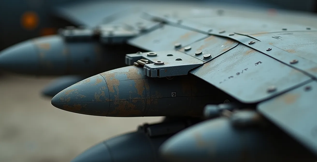
Training missiles, or “shapes,” are handled frequently, loaded and unloaded countless times. They are often heavily weathered, with chipped paint, scuffs, and worn stenciling. This provides an excellent opportunity for realistic weathering that tells a story of a high-tempo training environment, contrasting with the often pristine condition of a live missile loaded for a combat sortie.

The heavy wear seen on these training rounds is a direct result of repeated handling by ground crews. Capturing this texture is as important as getting the blue stripes correct for conveying a realistic training environment.
Why modern jets often fly with asymmetric loadouts (and why it looks cool)?
The belief that an aircraft must be perfectly symmetrical is a holdover from a bygone era. Modern fighters are equipped with sophisticated digital Flight Control Systems (FCS). These systems make thousands of micro-adjustments to the control surfaces per second, automatically compensating for any imbalance in weight or drag. As a result, asymmetric loadouts are not only possible but routine and tactically sound. A mission dictates the loadout, not a desire for perfect symmetry.
Consider a multi-role mission. An F-16 might be tasked with destroying a specific hardened target (requiring one heavy GBU-31 JDAM) while also being prepared for targets of opportunity (requiring several smaller GBU-12 Paveways). It makes no tactical sense to carry two heavy JDAMs if only one is needed, nor does it make sense to leave the lighter Paveways behind. The FCS manages the imbalance, allowing the pilot to carry the optimal mix of weapons for the expected threats. This asymmetry is a visual indicator of a complex, real-world mission profile.
Case Study: F-16 OIF Asymmetric Configuration
During Operation Iraqi Freedom, a common F-16C loadout for strike missions was highly asymmetric. A typical configuration consisted of a single 2,000lb GBU-31 JDAM on an inboard wing station, a targeting pod (LITENING or LANTIRN) on the intake hardpoint, and two 500lb GBU-12 laser-guided bombs on the opposing wing. This mix provided both a heavy, GPS-guided penetrator and lighter, more flexible laser-guided munitions, all balanced by the FCS. This loadout is a perfect example of mission-driven asymmetry.
This tactical flexibility means that as weapons are expended, the aircraft becomes progressively more imbalanced. The FCS handles this without issue. For the modeler, an asymmetric loadout is a mark of authenticity. It looks “cool” because it looks real. It reflects a deep understanding of modern air combat operations and is a clear rejection of the simplistic “Christmas tree” mentality.
How to simulate the glass lens on the tip of an infrared missile?
The seeker head is the eye of an infrared (IR) missile. Replicating its unique, iridescent look is a small detail that has a massive visual impact. A simple coat of gloss black is insufficient and looks toy-like. The actual seeker domes are made of materials like germanium or sapphire, coated with anti-reflective layers that produce a multi-hued, metallic sheen. Capturing this effect is a test of a modeler’s finishing skills.
There are several methods to achieve this, ranging in complexity. A basic but effective technique involves painting the seeker gloss black, then applying a clear gloss varnish to achieve a simple reflective surface. A more advanced approach yields far superior results. This involves starting with a bright metallic base, like chrome silver, and then building up thin, transparent layers of color. Tamiya’s “Smoke” (X-19) is an excellent product for this, as it darkens the lens without making it opaque. Over this, a whisper-thin mist of a clear color like purple or orange can create the desired iridescent shift.

The most advanced and convincing method is to use a drop of UV-curing resin to create a true, three-dimensional lens. This resin can be applied over a piece of chrome foil for maximum reflectivity and then tinted with transparent paints. This technique perfectly replicates the depth and complex optical quality of a real seeker head, turning a simple plastic part into a jewel-like centerpiece. Choose your method based on your skill and the level of detail you wish to achieve.
Tiered Approach to Missile Seeker Dome Finishing
- Standard Level: Apply a gloss black base coat. Follow with two thin coats of a high-quality clear gloss varnish (e.g., Alclad Aqua Gloss) for a basic reflective appearance.
- Advanced Level: Paint a metallic silver or chrome base. Apply Tamiya Smoke (X-19) in multiple thin, translucent layers. Finish with a final, very light tint of clear orange or purple to create an iridescent effect.
- Expert Level: Use a drop of clear UV-curing resin to create an actual dome shape. Back the dome with chrome foil before application. After curing, tint the resin with transparent colors for the most authentic germanium window appearance.
How to Design Simple Model Parts in CAD Without an Engineering Degree?
Inevitably, you will encounter a situation where the kit does not provide the correct pylon, adapter, or a specific weapon variant you need for your desired loadout. While kitbashing parts from other kits is an option, the ultimate solution for accuracy is to create the part yourself. With modern, user-friendly software and affordable 3D printing, designing simple parts in Computer-Aided Design (CAD) is no longer the exclusive domain of engineers.
The key is to focus on proportion and fit, not intricate detail. Software like Tinkercad is free, web-based, and designed for beginners. The process is straightforward: find good reference photos of the part you need from multiple angles. Military technical manuals and walkaround photo collections are invaluable resources. You then import a side-view photo into the CAD program, scale it to your model’s dimensions, and use basic geometric shapes (cubes, cylinders, wedges) to “trace” the object’s primary form. Pay close attention to the mounting points and overall silhouette. Small details like panel lines can be scribed later; the goal of the CAD process is to get the shape and size correct.
Once designed, the part is exported as an STL file for printing. For the fine details required in scale modeling, a resin printer is mandatory. These printers can achieve layer heights as low as 0.025mm, producing parts with a sharpness and quality that can rival or even exceed injection-molded plastic. This capability empowers you to create any loadout you can document, freeing you entirely from the limitations of what’s available in the box or on the aftermarket.
Jet Age vs Propellers: Which Era Offers the Best Learning Curve for Weathering?
The approach to weathering ordnance varies significantly between eras. While both demand skill, the nature of the challenge is different. A common perception is that WWII-era subjects are “easier” to weather because the effects—heavy chipping, mud, rust, oil streaks—are more dramatic and visually obvious. A beginner can apply these effects and see a clear, satisfying result. The canvas is simpler: bombs were typically a single, flat color, and the shapes were less complex.
Modern jet ordnance presents a different challenge: the weathering of subtlety. These weapons are often highly maintained and feature multiple materials and finishes on a single item. A Paveway bomb, for instance, has a cast metal body, a precision-machined guidance section, and delicate fins. The weathering is not about mud and rust, but about subtle stains from hydraulic fluid, scuff marks from handling carts, faded stencils from sun exposure, and the distinct sheen of different metallic and painted surfaces. The reference material is abundant, with high-definition photos available for almost any weapon system, but this also means that errors in weathering are more easily spotted by a discerning eye.
For a modeler looking to learn weathering, WWII ordnance provides a forgiving platform for mastering basic techniques like chipping, washes, and pigments. Modern ordnance, however, is a masterclass in finesse, texture, and observation. It forces you to study the real thing and replicate not just dirt, but the story of an object’s operational life.
| Aspect | WWII Ordnance | Modern Jet Ordnance | Learning Difficulty |
|---|---|---|---|
| Paint Types | Single flat color | Multiple finishes on same weapon | Modern: Higher |
| Weathering Effects | Mud, rust, heavy chipping | Subtle staining, worn stencils | WWII: Easier to see results |
| Detail Density | Simple shapes | Complex guidance kits, fins | Modern: More areas to weather |
| Reference Availability | Limited wartime photos | Abundant HD photos | Modern: Easier research |
Key Takeaways
- Physics First: A weapon’s weight and position on the wing are dictated by physics (moment arm, G-limits), not aesthetics.
- Time is Critical: Match all ordnance and aircraft modifications to a specific year or conflict to ensure historical accuracy.
- Mission Defines the Loadout: A weapon configuration is a direct reflection of the aircraft’s intended mission, making asymmetry a common and realistic feature.
Which Aftermarket Upgrade Offers the Best Visual ROI for Your Model Kit?
Once you have committed to a specific, realistic loadout, the next decision is how to execute it. Kit-supplied ordnance is often plagued by soft details, thick fins, and simplified shapes. This is where aftermarket upgrades become a critical force multiplier. However, not all upgrades are created equal. The goal is to invest your time and money where it will yield the maximum Visual Return on Investment (ROI). The focus should be on the most prominent and character-defining elements of the aircraft.
Without question, the highest ROI comes from two areas: the ordnance itself and the ejection seat. A set of sharply cast resin weapons will immediately elevate the model, replacing the kit’s soft plastic with crisp detail that becomes a focal point. Similarly, a resin ejection seat with molded-in harnesses is a night-and-day improvement over a basic, multi-part plastic seat and is visible through the canopy. These two upgrades alone account for the vast majority of a model’s visual impact.
Lower on the ROI scale are items like resin wheels and metal exhaust nozzles. While they are noticeable improvements, they are less central than the cockpit and weapons. At the bottom are fine photo-etch details for the cockpit interior or canopy framing. While valuable for a contest-level build, they offer diminishing returns for the average viewer. If the budget is limited to a single upgrade, the choice is clear: acquire one set of highly detailed, accurate resin weapons that will be the centerpiece of your realistic loadout. This single, strategic investment will have a greater impact than numerous smaller, less visible enhancements.
- Tier 1 – Maximum Impact (90% visual improvement): Resin weapons set replacing soft kit ordnance + Resin ejection seat with proper harness detail.
- Tier 2 – Noticeable Enhancement (60% improvement): Resin wheels with weighted effect + Metal exhaust nozzles replacing kit plastic.
- Tier 3 – Refinement (30% improvement): Photo-etch cockpit details + Canopy masks for perfect framing.
- Budget Option – Best single upgrade: One accurate resin weapon type that will be the centerpiece of the loadout.
Your mission is to build a statement of accuracy and intent. By applying these principles of physics, historical context, and tactical logic, you elevate your work from a simple assembly to a piece of meticulously researched military history. The next time you approach a new project, begin not with the cockpit, but with the mission. Define the purpose, select the loadout, and let that tactical decision guide every step of your build. Execute with precision.