Construction & Model Making
Building scale aircraft models transforms plastic and metal components into miniature representations of aviation history. Whether you’re assembling a Spitfire from the Battle of Britain or a modern jet fighter, the journey from box to display case demands mastery of numerous specialized techniques. Each step—from the initial cut that separates parts from their sprues to the final brushstroke of weathering—contributes to the visual impact and structural integrity of your finished model.
The difference between a satisfactory build and an award-winning replica often lies not in the kit itself, but in the builder’s understanding of fundamental construction principles. This comprehensive resource explores the essential techniques that form the foundation of quality model aircraft construction, addressing common challenges and offering practical solutions that work across different scales and manufacturers.
Planning Your Build Strategy
Before touching a single part, successful modelers invest time in understanding their kit’s architecture. Strategic planning prevents common pitfalls like trapped detail parts or assemblies that become impossible to paint properly.
Think of sub-assemblies as building blocks—the fuselage halves, wing sections, landing gear, and cockpit components each represent discrete units that can be worked on independently. This modular approach offers significant advantages: you can paint interior cockpit details without wrestling with an enclosed fuselage, or apply different paint schemes to wings before joining them to the body.
Batch processing elevates efficiency dramatically. Instead of following instructions linearly, experienced builders identify repetitive tasks and execute them simultaneously. Cutting all parts from sprues in one session, cleaning all attachment points together, or pre-painting all interior components saves time and ensures consistency. When you’re removing seams from ten identical rockets under an aircraft’s wings, working on all ten simultaneously with the same sanding stick guarantees uniform results.
Instructions serve as guides, not gospel. Manufacturers sometimes sequence steps for ease of molding or packaging rather than optimal construction. You might need to delay joining fuselage halves to access internal details, or paint certain components before assembly even when instructions suggest otherwise.
Part Preparation: Cutting and Cleaning
The moment you separate a part from its sprue defines its future finish. Clean cuts prevent surface damage that requires extensive repair later. Understanding plastic behavior during cutting prevents the white stress marks that appear when plastic is crushed or twisted.
Most experienced builders employ a two-cut method: first, cut approximately 2mm away from the part on the sprue, leaving a small stub. This initial cut bears the stress and potential damage. The second cut, made carefully at the actual attachment point with a fresh, sharp blade, removes the stub cleanly without stressing the part itself.
- Use dedicated sprue cutters for the first cut—their blunt tips prevent accidental surface scratches
- Reserve sharp hobby knives for final cleanup of attachment points
- Cut clear canopy parts with extra caution, as stress marks appear white and highly visible
- Maintain cutting tools regularly; dull blades crush plastic rather than shearing it cleanly
The attachment point left after cutting requires refinement. A file, sanding stick, or scraping motion with a fresh blade removes the residual nub. Work perpendicular to the part surface, checking frequently to avoid creating a depression where material once connected to the sprue.
Adhesives and Assembly Techniques
Selecting the appropriate bonding agent determines joint strength and appearance. Chemical welding—the process by which liquid cement partially dissolves plastic surfaces and allows them to fuse—creates bonds stronger than the surrounding material. Unlike white glues that simply stick surfaces together, these solvents literally merge parts at the molecular level.
The tube versus bottle debate centers on control and application method. Tube cement (often called “poly cement”) offers thick consistency ideal for filling small gaps while bonding. Liquid cement, applied with a fine brush, flows into tight joints through capillary action, creating invisible seams when parts fit precisely.
Each adhesive type presents specific challenges:
- Tube cement: Slow drying allows repositioning but can squeeze out visibly; requires careful cleanup
- Liquid cement: Fast-drying creates strong bonds quickly but allows no time for adjustment; excess can melt surface detail
- CA glue (cyanoacrylate): Bonds dissimilar materials but can fog clear parts with vapor; sets almost instantly
The phenomenon of “ghost seams”—visible lines that appear after painting despite careful sanding—haunts many builders. These occur when cement damage slightly roughens plastic adjacent to joints, creating a texture that catches paint differently than undamaged areas. Minimizing collateral damage requires precision application and immediate removal of excess adhesive before it spreads.
Optimizing cure times prevents premature handling. While liquid cement may feel dry in minutes, full strength develops over hours. Stressed joints—like long wing spans or heavy nose sections—benefit from overnight curing before further work.
Test Fitting and Alignment
Experienced modelers know that dry fitting reveals problems adhesive cannot solve. Assembling parts temporarily without glue exposes gaps, misalignments, and interference points that require correction before permanent bonding.
Walk around your dry-fitted assembly viewing from multiple angles. Gaps often hide along bottom seams or in shadowed areas, only to become glaringly obvious after paint highlights them. Identifying these locations early allows targeted filling with putty or shimming with plastic strip.
Temporary holding techniques include:
- Masking tape stretched across seams provides gentle, removable pressure
- Rubber bands work well for cylindrical assemblies like fuselage sections
- Clay or poster putty holds parts in position without bonding
- Spring clamps apply consistent pressure on flat surfaces
Aircraft models demand particular attention to dihedral angles—the upward angle of wings from root to tip. Most kits provide positive location for correct dihedral, but some require the builder to assess and maintain proper angles during glue curing. A simple technique involves measuring the distance from wingtip to work surface on both sides, ensuring symmetry.
Alignment pins, supposedly helpful, sometimes cause more problems than they solve. Misaligned or oversized pins force parts into incorrect positions. Don’t hesitate to remove problematic pins and align parts visually, using the overall profile as your guide. Similarly, modifying tabs—those small plastic guides that slot into corresponding holes—by thinning or shortening them often improves fit dramatically.
Surface Preparation and Finishing
Achieving seamless surfaces requires understanding grit progression—the systematic movement from coarse to fine abrasives. Starting with 320-grit removes excess putty and obvious seam lines; 600-grit smooths the surface; 1000-grit polishes to near-invisibility. Skipping grades leaves scratches that finer papers cannot remove efficiently.
Wet sanding revolutionizes surface preparation by suspending removed material in water, preventing scratches from abraded particles dragged across your work. The technique also allows use of finer grits than practical with dry sanding, and the water makes progress easily visible—wet surfaces temporarily show their final finish state.
Putty application challenges even experienced builders due to shrinkage issues. Most putties contract as solvents evaporate, creating depressions that require additional applications. The solution involves slight overfilling, allowing the putty to cure completely (often 24 hours despite surface drying), then sanding back to flush. Some builders apply putty in multiple thin layers rather than one thick application, reducing overall shrinkage.
Curved surfaces demand specialized tools—flat sanding sticks create flats where curves should be. Foam-backed abrasive sheets conform to gentle curves, while cylindrical objects (the handle of a paintbrush, sections of dowel) wrapped with sandpaper maintain fuselage roundness during seam removal.
Overly aggressive sanding inevitably removes panel lines or rivets adjacent to seams. Restoring lost detail requires rescribing—carefully re-cutting panel lines using specialized tools. Scribing tools range from purpose-made scribers with angled blades to repurposed sewing needles mounted in pin vises. The key lies in working slowly, using tape or templates as guides, and making multiple light passes rather than one deep cut.
Structural Reinforcement for Complex Assemblies
Some joints bear significant weight or stress—long landing gear legs, extended wing spans, or heavy nose sections packed with detail. Standard plastic-to-plastic bonding sometimes proves insufficient for long-term stability.
Metal cores inserted into hollow parts provide tremendous strength increases. A brass rod running through a landing gear strut prevents the splay that occurs when plastic alone supports a model’s weight. The process involves drilling through both parts to be joined, inserting rod slightly shorter than the drilled depth, then assembling with CA glue or epoxy.
Understanding splay angles—the tendency of joints to spread under load—helps predict where reinforcement proves beneficial. Wing root joints, tail plane attachments, and landing gear mounts all experience forces that work to open connections over time.
White metal parts (often used for landing gear in older or aftermarket sets) bond differently than plastic. Standard plastic cement won’t work; CA glue or epoxy becomes necessary. White metal offers superior strength but adds weight—sometimes advantageous for nose-heavy models requiring ballast, sometimes problematic for delicate mounting points.
When joint failure seems likely despite best efforts, building alignment jigs—temporary structures that hold parts in correct position during extended cure times—ensures accuracy. A simple jig might consist of scrap wood with parts pinned in place, allowing epoxy’s full cure cycle to complete without manually holding components for hours.
Detailing High-Visibility Areas
The cockpit dominates viewer attention on most aircraft models. Focal point detailing recognizes that not all areas warrant equal effort—concentrate your finest work where eyes naturally fall.
Dry brushing brings out cockpit details effortlessly. Load a flat brush with paint, wipe most of it onto paper towel until the brush seems nearly dry, then lightly stroke raised details. The technique deposits paint only on high points, creating instant shadows and highlights that suggest depth and wear.
Pre-painted photo-etched (PE) details offer incredibly fine instrument panels and structural elements, though they present installation challenges. The alternative—decal instrument panels—proves easier to apply but lacks the three-dimensionality of PE. Your choice depends on viewing distance and desired detail level.
Clear canopies reveal or hide your cockpit work—fogged, scratched, or poorly fitted canopies destroy the illusion regardless of interior quality. The primary risk involves chemical fogging from CA glue vapors or aggressive cements. Future floor polish (the acrylic floor finish widely used by modelers) applied in multiple thin coats restores clarity to slightly damaged canopies and provides a glossy, scale-appropriate finish.
Masking sequence for multi-part canopies requires planning: which frames get painted versus masked? Which sections install before painting versus after? Generally, attach and mask complex multi-pane canopies before painting the model, but leave simple one-piece canopies for final installation to prevent handling damage.
Advanced Painting: Airbrushing Camouflage
While brushes serve for detail work, airbrushing delivers the smooth, scale-appropriate finish that characterizes realistic aircraft models. Mastering paint thinning ratios forms the foundation—too thick causes spatter and clogging; too thin creates runs and poor coverage.
Most acrylic paints thin effectively at ratios between 1:1 and 2:1 (thinner to paint), but this varies by brand and specific color. The “milk test” provides a practical guideline: properly thinned paint flows with the consistency of whole milk. Test on scrap plastic before committing to your model.
Pressure settings balance coverage and overspray. Lower pressure (10-15 PSI) suits detail work and tight patterns but requires closer working distance. Higher pressure (20-30 PSI) covers larger areas quickly and atomizes paint finely but increases overspray risk.
- Needle size affects paint flow: fine needles (0.2-0.3mm) excel at detail and thin paints; medium needles (0.35-0.5mm) handle most general work; large needles (0.5mm+) suit primers and high-volume coverage
- Tip dry—paint drying on the needle tip—creates spatter and irregular spray patterns; prevent it by proper thinning and periodic cleaning
- Hand movement should maintain constant distance and speed; start motion before triggering paint and continue after releasing to avoid start/stop marks
Freehand camouflage application (painting without masks) creates soft-edged, realistic patterns impossible to achieve with hard masks. The technique demands practice: maintain 2-4 inches distance, use reduced pressure, build color gradually in multiple light coats, and visualize the pattern before beginning.
Decal Application Mastery
Even perfect construction and painting falls short without proper markings. Decal application transforms generic aircraft into specific historical examples, but the process challenges builders with numerous technical pitfalls.
The foundation for successful decaling involves a glossy base coat. Decals applied over flat or satin paint trap air in the microscopic texture valleys, creating silvering—a cloudy appearance that destroys realism. Spray a gloss clear coat over painted areas that will receive decals, even if your final finish will be matte.
Trimming carrier film close to printed areas minimizes silvering risk and reduces film visibility. The clear film surrounding decal artwork often extends far beyond necessary; careful cutting with fresh scissors or a new blade reduces excess film dramatically.
Mistakes happen: decals tear, position incorrectly, or fold during application. Recovery techniques include:
- Immediately re-wet problematic decals to restore flexibility
- Use decal setting solutions to soften film and allow repositioning
- Carefully lift edges with a damp brush rather than forceps, which often puncture film
- For damaged decals, consider painting replacements or sourcing aftermarket sheets
Trapped bubbles telegraph through decals as raised bumps. Pierce them with a sharp needle point while the decal remains wet, then apply setting solution and press the area flat. The tiny hole becomes invisible once sealed with clear coat.
Sealing decals with clear coat protects them from handling and integrates edges into the paint surface. Multiple thin coats work better than one heavy application—allow each coat to dry completely before applying the next.
Specialized Techniques: Fragile Decals and Data Markings
Vintage kit decals and modern waterslide decals in thin gauges demand extra care. Liquid decal film applied over old, fragile decals before cutting provides a protective layer that prevents disintegration during water immersion. This product essentially adds a new carrier film over deteriorated originals.
Water temperature significantly impacts decal behavior. Warm water releases decals faster, which seems advantageous until you experience a decal sliding completely off its backing before you’re ready. Room temperature or slightly cool water provides better control, especially for large or complex markings.
Modern aircraft models often include hundreds of tiny stencil data markings—maintenance instructions, warning labels, and technical data. Applying these individually becomes tedious, but several strategies help:
- Batch process by type: apply all similar markings in one session
- Visualize final placement by studying reference photos before starting
- Group related decals on the backing sheet to minimize searching
- Consider selective application—not every stencil appears on every aircraft; choose the most visible locations
Decaling over raised panel lines or rivets creates conformity challenges. Decal softening solutions dissolve film slightly, allowing it to snuggle into recessed detail and drape over raised features. Apply softener after positioning the decal, allow it to work for several minutes, then gently press with a damp cotton swab.
Final Touches: Rigging and Special Effects
The final details separate completed models from truly finished pieces. Rigging—the wires and cables visible on many aircraft—adds dramatic realism but requires steady hands and patience.
Material selection ranges from stretched sprue (heated plastic pulled into fine strands) to specialized elastic rigging thread and metal wire. Each offers advantages: stretched sprue costs nothing and paints easily; elastic thread maintains tension naturally; metal wire provides scale-appropriate rigidity.
Drilling blind holes (shallow depressions that don’t penetrate through) at rigging attachment points provides secure anchoring. A pin vise with fine drill bit creates precisely located holes that accept CA glue and rigging material. Ensure holes align correctly before drilling—test with straight pins first.
Tensioning keeps rigging straight and realistic. The material must pull taut without bending mounting points. Elastic rigging naturally maintains tension; other materials require careful adjustment during gluing.
CA glue vapors can fog clear parts even at final assembly stages. When rigging near canopies or other transparent components, use CA with extreme care, consider alternative adhesives like white glue, and ensure adequate ventilation.
Specialized effects like wood grain simulation add authenticity to aircraft featuring exposed wood structures. The process involves base color selection (appropriate wood tone), oil paint dragging (pulling thinned oil paint across the surface with a fine brush to create grain lines), and masking to create individual plank delineation. A clear orange-tinted topcoat adds warmth and depth to the simulated wood.
Each technique described here builds upon fundamentals while opening doors to increasingly sophisticated modeling. The journey from basic assembly to master-level finishing never truly ends—there’s always another technique to refine, another challenge to tackle, another aircraft waiting to be brought to life through patient, skillful construction.
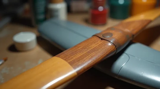
From Plastic to Patina: How to Paint a Masterpiece-Worthy Wood Grain Propeller
In summary: Achieve realism not with a single brown paint, but by building up chromatic depth using layered acrylics like tan, ochre, and even salmon as an undercoat. Treat oil paints as a sculpting medium, not just paint. Use a…
Read more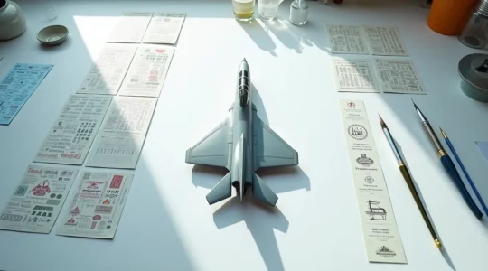
Applying Hundreds of Stencils: A Project Manager’s Guide to Avoiding Decal Fatigue
In summary: Treat mass decaling not as an artistic chore, but as a project to be managed with systems and logic. Divide the model into small, manageable sections and work in focused sessions to reduce cognitive load. Use a robust…
Read more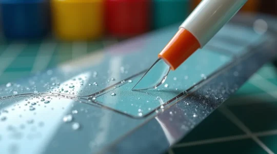
How to Save a Tearing Decal Before It Ruins Your Wing Marking?
In summary: Treat fragile decals like ancient manuscripts; reinforcement before handling is non-negotiable. Control the environment—use warm water and proper setting solutions to make the decal pliable, not brittle. Master delicate rescue techniques for when things go wrong, such as…
Read more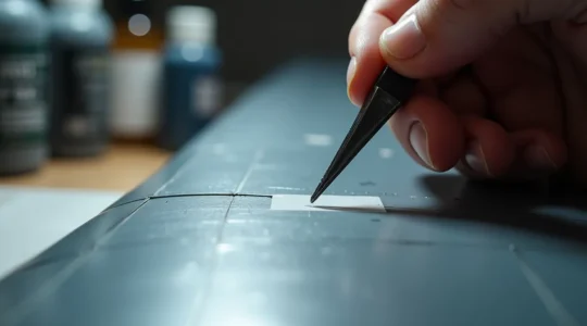
How to Prevent Decal Silvering on Matte Paint Surfaces?
Decal silvering isn’t a random failure; it’s a predictable optical effect caused by microscopic air pockets trapped under the decal film on an uneven surface. A mandatory, mirror-smooth gloss varnish is the only way to eliminate the surface’s rough micro-topography,…
Read more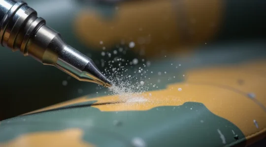
Mastering Freehand Soft-Edge Camouflage Without Splatter
In summary: Achieving a splatter-free soft edge relies on a trinity of control: highly thinned paint, low air pressure, and precise trigger discipline. Your paint must be thinned to the consistency of milk, often a 70% thinner to 30% paint…
Read more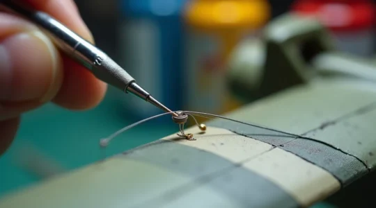
How to Install Fine Antennae Rigging Without Snapping Them Instantly?
In summary: Flawless rigging is a systematic process, not guesswork. The key is eliminating variables before you even touch the model. Choose your material based on its elasticity and resilience; Lycra thread offers superior durability against accidental bumps compared to…
Read more
Mastering Realistic Cockpits: Pro-Level Detailing for Modelers with Changing Eyesight
The secret to stunningly detailed cockpits, even with changing eyesight, isn’t perfect vision—it’s using clever “compensatory techniques” that make details pop without microscopic work. Swap pure black for dark greys to reveal, not hide, molded-in detail. Choose between sharp photo-etch…
Read more
How to Strengthen Plastic Landing Gear Legs for Heavy Resin Conversions?
The long-term structural integrity of a heavy model conversion depends not on quick fixes, but on applying engineering principles to systematically counteract the inevitable deformation of plastic under load. The primary failure mechanism is not sudden breakage but gradual “plastic…
Read more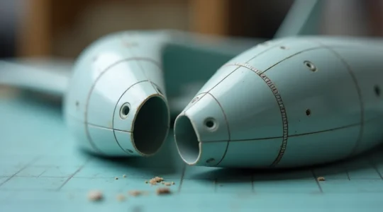
How to Align Fuselage Halves Perfectly When the Kit Is Warped?
The common advice to ‘just clamp it harder’ is why seams pop weeks later. A warped fuselage isn’t a glue problem; it’s a structural tension problem. The plastic has ‘memory’ and is constantly trying to revert to its warped shape,…
Read more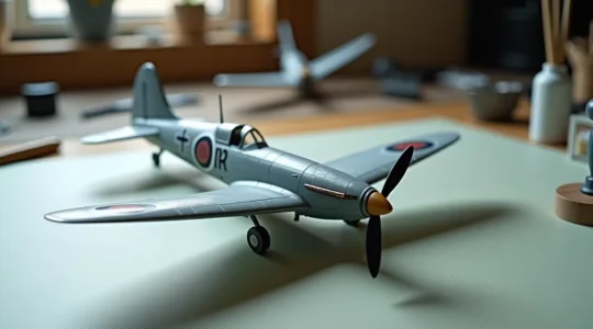
Raised vs Recessed Panel Lines: How to Handle Older Kits for a Modern Look?
The common advice to rescribe every raised panel line on a vintage kit is often counterproductive; the real art lies in a hybrid approach. True modernization involves “Selective Fidelity”: enhancing existing raised details and only scribing new lines where they…
Read more