A high-fidelity replica is not a shrunken aircraft; it is a meticulously engineered illusion that convinces the eye of its reality through the mastery of scale physics and material history.
- Authenticity is achieved by manipulating color to simulate atmospheric effects at scale, not by using factory-correct paint codes.
- Superior realism comes from suggesting structural details like ‘oil-canning’ rather than obsessively replicating every single rivet.
Recommendation: To elevate a build from accurate to authentic, one must stop thinking like a manufacturer and start thinking like a physicist and a historian.
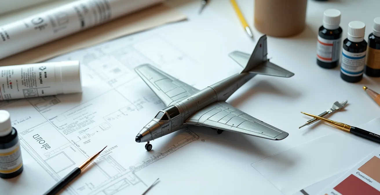
In the world of scale aircraft modeling, a line exists—fine yet absolute—that separates the merely accurate from the truly convincing. Many builders achieve accuracy. They use high-quality kits, follow instructions, and produce clean, well-assembled representations. Yet, when placed under the critical eye of a contest judge or a discerning collector, these models can feel strangely lifeless, like immaculate toys rather than miniature artifacts. They possess the form of the subject but lack its soul, its visual weight, and its history. The common advice to “be accurate” or “add weathering” is a gross oversimplification of a far more complex discipline.
The pursuit of a high-fidelity replica is not a journey toward literal, microscopic replication. That is a novice’s error. Instead, it is a venture into illusion and perception. It requires an understanding that a 1:48 scale model is not viewed from a 1:48 scale distance. The light that reflects from its surfaces, the colors perceived by the eye, and the textural details that register in the brain must all be deliberately manipulated to account for this discrepancy. The goal is not to build a tiny airplane, but to build a model that *feels* like a full-scale aircraft seen from a distance.
This distinction is the core principle of master-level modeling. It demands a shift in mindset from assembler to artist-engineer. It involves a deep dive into the physics of light, the science of historical research, and the narrative power of a weathered surface. This guide deconstructs the unwritten rules and advanced criteria that define a truly museum-quality piece, moving beyond the platitudes to articulate the specific standards that separate a good model from a breathtaking replica.
This article will dissect the core pillars of high-fidelity modeling. We will explore the science behind scale color, the forensic methods for blueprint verification, the strategic value of custom parts, and the critical balance between detail and realism that elevates a model to the highest standard.
Summary: The Anatomy of a Masterpiece Replica
- Scale effect explained: why exact color matches look wrong on small models
- How to find authentic blueprints when the kit instructions are wrong?
- Resin upgrade or DIY: which adds more value to a high-fidelity build?
- The “rivet counter” error that makes a model look unrealistic
- How to correct the wing dihedral angle on a warped fuselage?
- How to Research Historical Liveries When Archival Photos Are Black and White?
- Why Clean Models Look like Toys: Adding Authentic Weathering to Scale Aircraft?
- Why You Must Treat Resin Parts Differently Than Plastic to Avoid Lung Damage?
Scale effect explained: why exact color matches look wrong on small models
The most common error in high-end modeling is the dogmatic adherence to factory paint codes. A model painted with the exact RLM 76 used on a Messerschmitt Bf 109 will look cartoonishly dark and toy-like. This is not a matter of opinion, but of physics. The principle is called atmospheric perspective or “scale effect.” A column of air between an observer and a distant object contains microscopic particles of dust and moisture that scatter light, subtly desaturating and lightening the object’s appearance. A full-size aircraft is always viewed through a significant amount of atmosphere; a model is not. To create a convincing illusion, the modeler must paint this atmospheric effect onto the model itself.
This means deliberately altering the base colors. For smaller scales, the effect must be more pronounced. A 1:72 scale aircraft requires a greater percentage of white or a lightener added to its base colors than a 1:32 scale model. The same logic applies to sheen. Large, flat metal panels on a real aircraft do not reflect light uniformly. A model must replicate this with a “scale sheen,” a carefully modulated finish that is neither flat nor fully gloss, but a complex surface that breaks up light in a believable way. Ignoring this principle is the fastest way to make an otherwise perfect model look artificial.
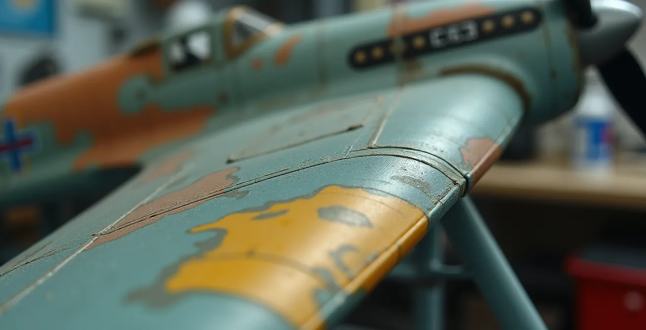
As the illustration demonstrates, the effect is achieved through subtle variations. Panel tone variation—altering the shade of adjacent panels by a mere 3-5%—simulates replacement parts and paint batch differences that are ubiquitous on operational aircraft. Furthermore, applying highly thinned filter layers of blue-grey can simulate the atmospheric haze on surfaces that would appear more distant to an observer, such as lower wings or tail planes. This is not “weathering”; it is the foundational work of creating a believable canvas before any weathering even begins.
How to find authentic blueprints when the kit instructions are wrong?
A high-fidelity replica is built upon a foundation of truth. Unfortunately, the plastic in the box is often an interpretation, not a fact. Kit manufacturers, even reputable ones, are prone to errors, simplifications, or basing their designs on inaccurate sources. A serious modeler must assume the role of a forensic historian, treating the kit’s plans as a starting point for investigation, not as gospel. The objective is to bypass the chain of commercial interpretations and get as close as possible to the primary source: the original factory drawings or official maintenance manuals.
This requires a disciplined approach to sourcing. Not all information is created equal, and relying on other modelers’ plans found on forums can often lead to propagating the same errors you seek to correct. A clear hierarchy of reliability must be established.
The following table outlines the hierarchy of source reliability for aircraft blueprints. A judge expects a build to be based on evidence from the top tiers of this hierarchy.
| Source Type | Reliability Score | Typical Access Method | Common Issues |
|---|---|---|---|
| Original Factory Drawings | 95-100% | Museum archives, manufacturer records | May show prototypes, not production versions |
| Official Maintenance Manuals | 90-95% | Military archives, technical libraries | Can reflect field modifications |
| Period Primary Photos | 85-90% | Historical societies, veterans collections | Perspective distortion, unclear details |
| Academic Publications | 75-85% | University libraries, scholarly journals | May contain interpretation errors |
| Other Modelers’ Plans | 50-75% | Modeling forums, hobby magazines | Often propagate kit manufacturer errors |
Case Study: The Digital Overlay Verification Technique
Once a reliable blueprint is acquired, it must be used to verify the kit’s accuracy. A masterclass method for this is the digital overlay. According to a detailed process from FineScale Modeler, this involves scanning kit parts at high resolution (e.g., 600 DPI) and superimposing them as a semi-transparent layer over the verified blueprints in image editing software. This technique has revealed significant flaws in popular kits, such as a 1:48 P-51D model with wing root angles off by 2.5 degrees and a fuselage 3mm too short. Only by identifying these flaws can a modeler begin the corrective work—using shims, sanding, and rescribing—that separates a high-fidelity build from an out-of-the-box assembly.
Resin upgrade or DIY: which adds more value to a high-fidelity build?
The question of using aftermarket resin parts versus scratch-building a detail is often framed as a choice between convenience and craftsmanship. This is a false dichotomy. For the serious collector, the only relevant metric is the final result. The question is not “how was it made?” but “does it achieve a level of fidelity impossible with the base kit?” From a judge’s perspective, value is added when a detail is both exquisitely rendered and corrects a flaw or adds a layer of complexity the kit manufacturer omitted. Both resin and DIY methods can achieve this, but the highest value lies in a hybrid approach that leverages the best of both.
Commercial resin sets offer incredible precision for common upgrades like cockpits or engines. Their value is in providing a baseline of high detail that would be prohibitively time-consuming to create from scratch. However, they can be generic. The true mark of a master-level build is often the bespoke detail—the specific modification or piece of equipment unique to the individual aircraft being modeled, which no aftermarket company produces. This is where DIY, or more accurately, personalized digital fabrication, becomes essential.
Case Study: Personalized Digital Fabrication Success
The modern craftsman does not simply choose between a resin part and a piece of styrene. They design the exact part they need. A project documented by Paul Budzik’s Scale Model Workshop demonstrated a breakthrough where custom engine pushrod details for a 1:32 F4U Corsair were designed in CAD software and printed on a high-resolution resin 3D printer. These parts, accurate to 0.1mm, did not exist in any commercial set. This approach combines the narrative value of scratch-building (creating a unique part) with a level of precision that surpasses even the best commercial offerings. This build won Best Aircraft at the IPMS Nationals, proving that the ultimate value lies not in the method, but in the uncompromising pursuit of a specific, correct detail.
Therefore, the debate is obsolete. A high-end build should feature the best commercial resin where it saves time without compromising accuracy, and leverage DIY or digital fabrication to create the unique, defining details that tell the specific story of that one airframe. One must use the tool that best achieves the perfect result.
The “rivet counter” error that makes a model look unrealistic
There is a pervasive myth among intermediate modelers that more detail equals more realism. This leads to the “rivet counter” fallacy: the obsessive replication of every fastener on an aircraft’s skin. The result is often a model that looks like a technical drawing, not a real object. Its surface is busy, textured, and fundamentally wrong. From a normal viewing distance, the vast majority of flush rivets on a painted aircraft are invisible. Accentuating them on a small-scale model is a grotesque exaggeration. It violates the principle of scale perception.
True realism lies in restraint and the suggestion of detail. The human eye is fooled by overall effect, not by a granular accounting of parts. A much more convincing effect than a grid of rivets is the subtle replication of “oil-canning” or “stressed skin.” This refers to the slight buckling and waviness of thin metal panels between the structural ribs of an airframe. This effect catches the light and tells the brain this is a large object made of thin, tensioned metal, not a solid piece of plastic.

Case Study: Achieving Realism Through ‘Oil-Canning’
A masterclass technique featured in FineScale Modeler demonstrates this principle. Instead of adding rivets, the modeler works from the inside of the fuselage halves before assembly, using a heated, rounded tool to gently press the plastic outwards between the frame lines. This creates a subtle, non-uniform surface deformation. When painted, this surface catches raking light in a highly realistic manner, suggesting the underlying structure without explicitly showing it. This ‘stressed skin’ effect provides a profound sense of realism and material honesty that a perfectly flat, rivet-covered surface can never achieve.
This does not mean all surface detail is wrong. The key is scale-appropriateness. What is visible on a 1:24 scale model is wholly inappropriate for 1:72. The “three-foot rule” is a crucial final check: if the rivet detail is the first thing you notice from arm’s length, it is overdone and must be reduced. True mastery is knowing what to leave out. As a guide, following scale-dependent visibility guidelines is not a suggestion, but a requirement for realism.
How to correct the wing dihedral angle on a warped fuselage?
Among the most critical yet often overlooked aspects of an aircraft’s form is its “sit” or posture. A fundamental component of this is the wing dihedral—the upward angle of the wings from the root to the tip. This angle is engineered for aerodynamic stability and is a defining characteristic of an aircraft’s silhouette. Even a small error of one or two degrees can make a model look inexplicably “wrong,” even to an untrained eye. Warped fuselages or poorly engineered kit parts are common culprits that can destroy this crucial angle.
Simply gluing the wings on and hoping for the best is unacceptable. Forcing a warped part into place with glue and clamps will create permanent stress in the plastic, leading to seam splits or cracking years later. A professional approach requires a structural solution that guarantees perfect, symmetrical, and permanent alignment. The only way to achieve this is by building a precision alignment jig. This is not an optional tool; it is a fundamental piece of equipment for anyone serious about achieving structural accuracy.
A proper jig does more than just hold parts. It is a measurement and verification device, built using the authentic dihedral angles taken from verified blueprints. It allows the modeler to set the precise angle for each wing and ensure the fuselage is perfectly aligned on the centerline while the glue cures, free of any stress.
- Create a Base Platform: Start with a perfectly flat surface, like 12mm foam board or MDF, verified with a precision level.
- Transfer Angles: Use a protractor to transfer the exact dihedral angles from your verified blueprints onto vertical supports. A typical low-wing fighter might have 5-7 degrees, while a mid-wing jet could be nearly flat at 0-2 degrees.
- Build Wing Cradles: Construct adjustable cradles from LEGO Technic beams or wooden blocks. These should hold the wings securely at the correct angle without putting pressure on the delicate trailing edges.
- Install Centerline Guides: Use vertical brass rods or carbon fiber tubes to ensure the fuselage is held perfectly vertical and on the centerline, preventing any twist.
- Add Reference Points: A tutorial on the Balsa USA website suggests adding measurement points along the jig to verify wingtip height and ensure perfect symmetry during assembly.
Using a jig transforms the process from guesswork into an engineering procedure. It removes all stress from the joints as they cure, resulting in a perfectly true and stable airframe that honors the subject’s intended design. A model with a corrected dihedral has a powerful, authentic posture that no amount of surface detail can replicate if the core geometry is flawed.
How to Research Historical Liveries When Archival Photos Are Black and White?
Determining the correct colors and markings for a historical aircraft is a significant challenge, especially when the only available references are black and white photographs. A common mistake is to guess colors based on relative grayscale values. This approach is deeply flawed because it fails to account for the properties of the film used. Early photographic emulsions were not equally sensitive to all colors of the spectrum, a fact that must be understood to perform accurate color deduction.
Much of the photography from the 1930s and early 1940s was shot on orthochromatic film. This type of film was primarily sensitive to blue and green light but was almost completely blind to red. Consequently, red objects appear as nearly black in orthochromatic prints, while blue objects appear very light. This explains why the red in a German Balkankreuz or a British RAF roundel often looks black in period photos. Without this knowledge, a modeler could easily make a catastrophic error in livery interpretation.
Case Study: Orthochromatic Film Interpretation
The key to deciphering these images is cross-referencing. By knowing the known colors of national insignia, a researcher can establish a baseline for how the film rendered those colors. As a deep dive into film sensitivity explains, if the red in an RAF roundel appears black, and an unknown squadron marking on the same aircraft has the same grayscale value, it is highly probable that the unknown marking was also red. Conversely, a light gray marking might correspond to a shade of blue. This comparative analysis transforms guesswork into a scientific process of deduction.
However, visual evidence is only one part of the puzzle. When photos are ambiguous, the researcher must become a textual archaeologist, hunting for non-visual clues. This involves a systematic search for written documentation that can provide the missing color information.
- Squadron Operational Records: Held in national archives, these often contain written descriptions of special markings or camouflage schemes.
- Pilot Logbooks and Memoirs: Personal accounts frequently contain descriptive phrases like “my blue-nosed bird” or “the yellow-tailed Mustang,” providing invaluable clues.
- Factory Delivery Manifests: These documents can list the exact paint codes and markings applied to an airframe before it left the factory.
- Maintenance Logs: These records document repainting, repairs, and camouflage changes made in the field, explaining variations from standard liveries.
Why Clean Models Look like Toys: Adding Authentic Weathering to Scale Aircraft?
A factory-fresh model, no matter how accurately assembled and painted, is an incomplete story. It represents the aircraft for the brief moment it left the production line, but it fails to capture its operational life. Real aircraft are tools that exist in a harsh world of sun, rain, sand, and mechanical stress. This history becomes etched onto their skin. Narrative weathering is the art of replicating this story, transforming the model from a sterile object into a convincing artifact.
Authentic weathering is not the random application of dirt. It is a logical, systematic process dictated by the aircraft’s environment and function. An F-4 Phantom based in humid, salty Southeast Asia would exhibit vastly different aging patterns than a MiG-15 on the frozen Russian Front. The first step in any weathering project is to research the specific operational environment of the subject aircraft. Each theater of operations imposes a unique signature of wear and tear.
| Theater | Primary Effects | Color Shifts | Texture Changes |
|---|---|---|---|
| Pacific Islands | Salt spray, extreme sun | Blue-grey fading, white salt deposits | Pitted surfaces, coral dust accumulation |
| Russian Front | Mud, snow, exhaust | Brown/grey staining, soot black | Caked mud on gear, frost patterns |
| North Africa | Sand abrasion, heat | Paint stripped to metal, tan dust | Sandblasted leading edges, oil leaks visible |
| Northern Europe | Rain, industrial soot | Dark streaking, rust tones | Water stains, exhaust patterns |
Beyond environmental effects, weathering must reflect the aircraft’s function. Panel lines around engines will show more grime and oil leakage. Areas walked on by ground crew will have a different sheen and more chipping. Gun ports will be stained with cordite, and exhaust trails will follow the airflow over the wings and fuselage. This is where the modeler becomes a storyteller, ensuring every stain, chip, and fade has a logical cause. Advanced techniques go beyond simple washes and pigments to create physical texture, adding another layer of realism.
Case Study: Advanced Textural Weathering
To create the most convincing replicas, master modelers replicate not just the look of wear, but the physical texture. The “salt chipping” technique is a prime example. By applying salt crystals over a primer coat before the top color is sprayed, the modeler can then brush the salt away, revealing authentic, multi-layered paint chips with real physical depth. This can be combined with other textural effects, such as using a heated needle to replicate small-caliber flak damage or a rounded tool to impress dents into the surface. This multi-layered approach creates genuine tactile character, giving the model a visual weight that makes it feel substantial and real.
Key takeaways
- Scale perception is a physical reality; colors must be deliberately lightened and desaturated to create a convincing illusion, not matched to factory specifications.
- True accuracy is born from forensic research using primary sources like factory drawings, not from trusting the kit’s instructions.
- The “rivet counter” fallacy destroys realism; suggesting underlying structure through effects like oil-canning is vastly superior to a literal, exaggerated replication of every fastener.
Why You Must Treat Resin Parts Differently Than Plastic to Avoid Lung Damage?
In the pursuit of ultimate fidelity, many modelers turn to resin aftermarket parts for their superior sharpness and detail. However, this material is fundamentally different from the polystyrene of a standard kit, and that difference is not just in its working properties—it’s in its toxicology. The dust created from sanding, cutting, or grinding resin parts is a serious respiratory hazard. Unlike plastic shavings, which are relatively large, resin dust is a fine, airborne particulate that can be easily inhaled deep into the lungs, where it can cause chronic inflammation, scarring, or worse. Treating resin like plastic is an act of gross negligence.
A craftsman’s most important tool is their health. Any modeler working with resin parts, no matter how infrequently, must adopt a professional safety protocol. This is not optional, nor is it a sign of weakness. It is the mark of a professional who respects their craft and their own well-being. The cavalier attitude of “it’s just a little dust” has no place in a serious workshop.
Sanding polyester is dangerous and you should wear a dust mask. The dust is quite toxic, as are the fumes released when molding and casting. Urethane and polyester resins are nasty stuff. Epoxy is more benign, but don’t breathe dust from that, either. Always wear a dust mask or respirator when sanding.
– RPF Costume and Prop Maker Community, Professional Safety Discussion Forum
Beyond the health risks, resin has different physical properties. It is more brittle than plastic and can shatter under stress. Joints must be reinforced with metal pins (brass or steel rod) to provide structural strength. Furthermore, resin parts are cast in silicone molds that require a mold release agent to prevent sticking. This oily residue is invisible but will repel paint with absolute certainty. Every resin part must be meticulously cleaned with a powerful degreaser, like 99% isopropyl alcohol or automotive-grade cleaners, before any primer is applied. Skipping this step will guarantee paint adhesion failure.
Action Plan: Professional Safety Protocol for Resin Part Handling
- Equip Proper Respiration: Use a half-face respirator equipped with cartridges that block both organic vapors and fine particulates (P100). A simple N95 dust mask is entirely inadequate as it does not filter chemical vapors.
- Control Dust at the Source: Whenever possible, wet sand resin parts. Using water or oil during sanding prevents the fine dust from becoming airborne, which is the primary route of exposure.
- Implement Air Extraction: For any dry sanding or grinding, work in a well-ventilated area, ideally using a downdraft sanding station. A DIY version can be made with a simple box and an exhaust fan vented to the outside.
- Degrease Meticulously: Before priming or painting, thoroughly scrub every resin part with 99% isopropyl alcohol or an equivalent degreaser to remove all traces of mold release agent.
- Reinforce All Structural Joints: Drill and pin all major joints (wing roots, tailplanes, landing gear) with brass or steel rod to prevent the brittle resin from cracking or snapping under its own weight over time.
Mastering these advanced principles is the true path to creating a high-fidelity replica. It is a discipline that requires the mind of an engineer, the eye of an artist, and the patience of a historian. By moving beyond the kit and embracing the challenge of creating a convincing illusion, you can elevate your work to the standard demanded by serious collectors and judges alike.