Achieving realistic lighting in scale models is less about artistry and more about micro-engineering precision.
- Electrical safety is paramount: Always use a resistor calculated for your specific LED and power source to prevent melt-downs and ensure longevity.
- Light control is everything: Use layered paint techniques and physical barriers to eliminate light bleed and direct photons exactly where they are needed.
Recommendation: Treat each lighting element as a modular, testable sub-system before you even think about gluing the fuselage halves together.
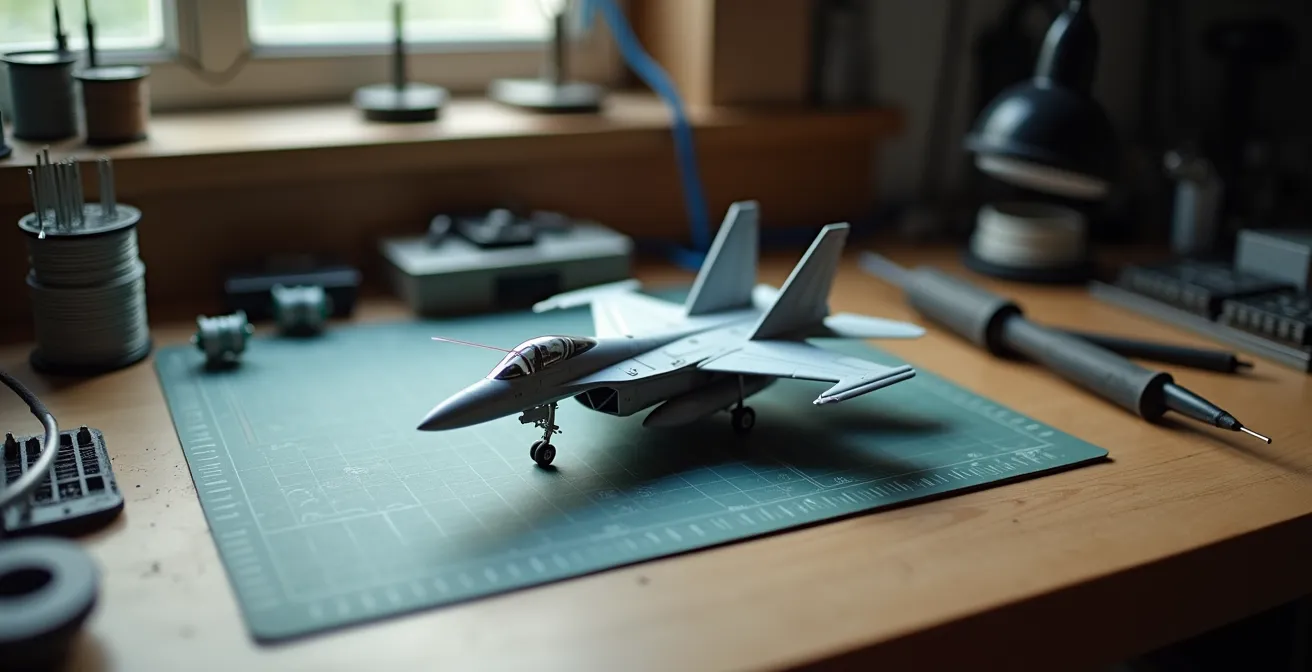
Bringing a static aircraft model to life with lights is a transformative step. It elevates a plastic replica from a simple desktop ornament to a dynamic, realistic miniature. Many modelers are drawn to the idea of a glowing cockpit or blinking navigation lights, but often hesitate, intimidated by the perceived complexity of electronics. The common advice to “just glue an LED inside” is a path to disappointment, often leading to melted plastic, unrealistic toy-like glows, and dead batteries.
The truth is, successful model illumination isn’t about being an electronics wizard. It’s about adopting a methodical, surgical approach to a series of small, manageable problems. It requires thinking less like a hobbyist and more like a micro-engineer. The key isn’t simply adding components, but mastering the systems that control them: managing heat, directing light paths, and planning power distribution with purpose and foresight.
This guide demystifies the process by breaking it down into its core engineering principles. We will move beyond simple tips to explore the ‘why’ behind the ‘how’. We’ll cover the essential physics of LEDs, the precise techniques for installing fiber optics, the strategic choices for power, the methods for achieving absolute light control, and the logic of modular wiring. By the end, you will have a clear framework for integrating complex lighting systems into your models with confidence and precision.
text
This article provides a structured path, from understanding the fundamental components to mastering advanced assembly and finishing techniques. Explore the sections below to build your expertise systematically.
Summary: Advanced Lighting and Building Techniques for Aircraft Models
- Why resistors are crucial to prevent LEDs from melting the plastic?
- Pin Vise techniques: how to drill 0.5mm holes for fibers in dashboards?
- Portability or Brightness: should your display be tethered to a wall socket?
- How to paint the interior black to prevent the whole wing from glowing?
- When to solder connections: before or after painting the fuselage?
- How to Paint Realistic Cockpit Instruments in 1:How to Start Building Static Aircraft Models Without Spending Over $100?
- How to Start Building Static Aircraft Models Without Spending Over $100?
- How to Transition from Static Modeling to RC Flying Without Crashing Your First Build?
Why resistors are crucial to prevent LEDs from melting the plastic?
At the heart of every successful model lighting project is a component that costs pennies but saves dollars in damage: the resistor. An LED (Light Emitting Diode) is not a tiny light bulb; it is a semiconductor that has a very specific operating voltage and current. Connecting an LED directly to a power source like a 9V battery is like opening a fire hydrant into a teacup. The unrestricted flow of current will overwhelm the diode, causing it to burn out in seconds and generate enough heat to visibly warp or melt the surrounding styrene plastic.
The resistor’s job is to “resist” this flow of electricity, limiting the current to the LED’s safe operating level, typically around 20 milliamperes (0.020A). This process of thermal management is non-negotiable. Without it, you not only risk destroying the LED but also undoing hours of careful assembly and painting work. In fact, engineering calculations show that LEDs driven at 30mA instead of a rated 20mA can have their lifespan reduced by 75%. This means a light designed to last for years might fail in a matter of months, long after the model is sealed up.
Choosing the correct resistor is a simple calculation based on Ohm’s Law: R = (V_source – V_led) / I. In simpler terms, you subtract the LED’s forward voltage from your power source’s voltage, then divide by the desired current (0.020A). For an advanced modeler, this isn’t just a chore; it’s the first step in designing a reliable, long-lasting electronic system.
Pin Vise techniques: how to drill 0.5mm holes for fibers in dashboards?
Once you decide to light up a tiny 1:72 scale cockpit, you enter the world of micro-drilling. Fiber optic strands, often as thin as 0.25mm to 0.5mm, are the only way to replicate the pin-prick lights of an instrument panel. The tool for this task is the pin vise, a handheld drill that allows for surgical control. However, drilling a clean hole smaller than a millimeter without cracking the delicate plastic dashboard is a technique in itself.
The primary mistake is applying pushing pressure. A micro-drill bit is incredibly brittle and will snap instantly. The correct method is a patient, twisting motion, letting the bit’s sharp flutes do the cutting. To prevent the bit from “wandering” on the smooth plastic, always create a pilot point first. A firm press with the tip of a sharp #11 scalpel blade or a sewing needle creates a tiny divot that will guide the drill bit perfectly. This ensures your hole is exactly where you intended.
Professional Technique: The Pilot and Twist Method
Experienced modelers working with intricate lighting often choose a drill bit slightly larger than the fiber to allow for a drop of adhesive. For instance, for common 64-strand fiber optics, they recommend using a #79 drill bit (0.37mm). The key is the sequence: first, mark the location with a sharp point. Second, place the drill bit in the mark. Third, gently twist the pin vise between your thumb and forefinger with zero downward pressure, letting the tool’s own weight and sharpness do the work. This method prevents plastic stress, cracking, and bit breakage.
This level of precision is what separates a good model from a great one. Visualizing the process is key to understanding the delicacy required.

As you can see in this close-up, the curling of the plastic shavings indicates a clean cut, not a forced puncture. Mastering this gentle, rotational technique is fundamental for any advanced modeler looking to integrate fiber optics effectively. It is a pure application of patience and control.
Portability or Brightness: should your display be tethered to a wall socket?
Choosing a power source for your model is a strategic design decision, not an afterthought. The choice dictates the model’s ultimate function and display potential. Will it be a self-contained piece you can pick up and examine from all angles, or a brightly lit centerpiece in a permanent diorama? This is the core trade-off between portability and brightness. Each power source comes with a distinct set of characteristics that you must weigh.
Battery options, from tiny coin cells to 9V or AAA packs, offer complete freedom. They are perfect for competition models or displays where wires would be distracting. However, they come with finite life, lower voltage (which can limit the number and brightness of LEDs), and the long-term hassle of replacement. A CR2032 coin cell might be perfect for lighting a single cockpit instrument, but it will struggle to power wing navigation lights and an afterburner effect simultaneously.
On the other hand, a tethered solution, like a USB power bank or a dedicated wall adapter (typically 5V or 12V DC), provides unlimited, consistent power. This allows for far brighter LEDs and more complex circuits without fear of dimming. This is the ideal choice for dioramas or display cases where the model is stationary. The challenge becomes hiding the wire, often routed through a landing gear strut or a custom display stand.
To make an informed decision, it’s essential to compare the options directly, as detailed in a comparative analysis on modeling forums.
| Power Source | Best For | Runtime | Brightness | Cost |
|---|---|---|---|---|
| Coin Cell (CR2032) | 1-2 LEDs, small models | 8-12 hours | Low | $2-3 |
| AAA Battery Pack | 3-6 LEDs, medium models | 20-30 hours | Medium | $5-10 |
| 9V Battery | 5-10 LEDs, complex lighting | 10-15 hours | High | $8-12 |
| USB Power Bank | Display bases, multiple models | 50+ hours | High | $15-25 |
| Wall Adapter (12V DC) | Permanent displays, dioramas | Unlimited | Very High | $10-20 |
Some advanced modelers even create hybrid solutions. For example, using small magnets and pogo pins embedded in the landing gear and a display base allows for seamless power transfer from a wall adapter when the model is on its stand, but preserves its clean, wire-free look when picked up. This “best of both worlds” approach embodies the engineering mindset.
How to paint the interior black to prevent the whole wing from glowing?
One of the most common and disappointing failures in model lighting is “light bleed.” This occurs when the light from an internal LED shines *through* the plastic, causing an entire wing, fuselage, or nacelle to glow like a cheap toy. Styrene plastic, especially in lighter colors, is translucent. The solution is not just to paint the interior, but to create a completely opaque barrier. This requires a specific, two-layer approach to ensure total light integrity.
The standard practice of simply spraying the interior with flat black paint is often insufficient. A single layer, especially if airbrushed thinly, can still allow bright LED light to pass through. The professional technique involves a more robust system:
- The Reflective Layer: First, apply a thick, opaque coat of silver paint (or even chrome) to all interior surfaces that will house lighting. The purpose of this layer is not to block light, but to reflect it. It acts like the inside of a flashlight reflector, bouncing all available photons back towards the intended exit point, such as a fiber optic tip or a clear lens. This maximizes brightness where you want it.
- The Opaque Layer: Once the silver coat is fully cured (allow 24 hours), apply a thick, brushed-on layer of flat black acrylic paint over it. A brushed coat provides a much thicker, more light-proof barrier than a sprayed coat. The black layer absorbs any light that gets past the silver, effectively eliminating any chance of light bleed.
Before closing up the model, always test your work. In a dark room, place the LED inside the fuselage half and turn it on. Any “hot spots” or areas that still glow faintly should be marked with a pencil and given another coat of black paint. For extremely tight or curved areas where painting is difficult, using a self-adhesive material like Bare-Metal Foil can provide a perfect, gap-free light block.
Advanced Technique: The Internal Light Box
For models with dense lighting, such as a sci-fi ship with hundreds of windows, modelers often go a step further. As noted in builds like those found on specialist forums like Starship Modeler, they construct dedicated “light boxes” from 0.5mm styrene sheets. These small, black-painted boxes are built around the LED clusters inside the model. This technique channels 100% of the light output directly into a bundled group of fiber optics while physically preventing any stray light from illuminating the model’s interior, ensuring absolute light control.
When to solder connections: before or after painting the fuselage?
The timing of your soldering and wiring is a critical strategic decision that dictates the entire workflow of your build. The amateur approach is to build the model completely and then try to thread wires through it. This inevitably leads to frustration, broken connections, and damage to the finished paint job. The professional, surgical approach is to embrace modular sub-assembly wiring. This means treating every lighted section—the cockpit, the wingtip lights, the engine nacelles—as a separate, complete, and testable electronic module.
This methodology requires you to plan your wiring from the very beginning. Before gluing the main fuselage halves, you should be creating channels for the wires to run through, often by gluing thin strips of 1mm styrene along the interior walls. This prevents a “rat’s nest” of wires that could interfere with fit or become pinched.
The core of this strategy is the use of micro-connectors, such as JST-SH or PicoBlade types. Each sub-assembly (e.g., the completed cockpit tub) is wired to its own connector. This allows you to fully build, paint, weather, and test the cockpit lighting in isolation. Once the main fuselage is painted and ready for final assembly, you simply feed the connector through a pre-planned opening and “plug in” the cockpit. This decouples the delicate painting process from the potentially messy soldering and wiring process.
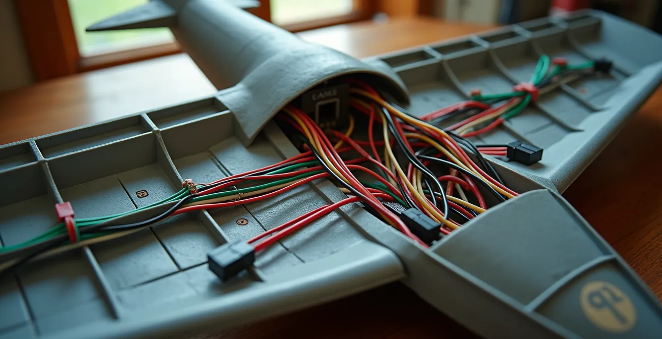
As illustrated, a well-planned interior shows wires routed neatly through dedicated channels, converging at micro-connectors. This organized system is not only more reliable but also makes troubleshooting and final assembly infinitely easier. Soldering is done early, on the workbench, not late, inside a nearly-finished model.
Action Plan: Modular Sub-Assembly Wiring Sequence
- Stage 1: Complete and fully test the cockpit lighting module with all its connections before installing it into the fuselage.
- Stage 2: Wire the navigation lights as a separate, testable unit, leaving 2cm wire leads for flexible connection.
- Stage 3: Install micro-connectors (like JST-SH or PicoBlade) onto each sub-assembly’s wiring harness for easy plug-and-play final assembly.
- Stage 4: Create dedicated wire channels using 1mm styrene strips glued along the fuselage interior to guide and protect wiring.
- Stage 5: Perform a full-circuit test of all sub-assemblies connected together *before* closing and gluing the main fuselage halves.
How to Paint Realistic Cockpit Instruments in 1:How to Start Building Static Aircraft Models Without Spending Over $100?
A beautifully lit cockpit is let down if the instrument dials themselves look flat and lifeless. Achieving a sense of depth and realism, with a “glass” effect over the dials, is a finishing touch that signifies an advanced level of skill. While the title mentions a budget, high-end results are achievable with patient technique rather than expensive tools. The key is a multi-layered approach that combines painting, decals, and gloss varnish.
The most effective method involves “sandwiching” decals and paint. Here is a reliable sequence for creating that coveted glass-lens look on an instrument panel:
- Apply Decals First: After painting the main panel surface (typically a dark grey or black), apply the individual instrument dial decals as per the kit instructions.
- Create the Lens: Once the decals are set, apply a single, generous drop of clear gloss varnish directly over each dial. Products like Aqua Gloss or even the floor polish Future/Pledge work perfectly. The varnish’s surface tension will cause it to form a perfect, dome-shaped “lens.”
- Cure and Paint Over: Allow the gloss to cure completely for at least 24 hours. Once hard, you can paint the final color of the instrument panel right over the entire surface, including the newly created lenses.
- The Reveal: Finally, take a cotton swab barely moistened with enamel thinner or alcohol (depending on your paint type) and gently wipe the paint off the top of the gloss domes. The paint will be removed from the raised “glass” lens, revealing the decal underneath, while remaining in the surrounding panel.
For an even greater boost in realism, a final dry-brushing with a light grey or silver paint will catch the raised edges of switches and bezels, creating highlights and a sense of three-dimensional detail. For those willing to spend a little, aftermarket parts can provide a significant upgrade. Scale modelers often report that photo-etched or 3D-printed instrument panels, which can cost as little as $8-15, offer far superior detail and are a cost-effective way to elevate a standard kit to a competitive level.
How to Start Building Static Aircraft Models Without Spending Over $100?
While this guide focuses on advanced techniques, every expert started with a first kit. It’s a common misconception that you need an expensive airbrush and a workshop full of tools to begin. In reality, you can assemble a high-quality “starter toolkit” that will produce excellent results and serve you well into more complex projects, all while staying under a $100 budget. The key is to invest in a few quality core items and supplement them with clever, inexpensive alternatives.
The most important choice is the kit itself. Opt for a modern, new-tool kit from a brand like Airfix, Revell, or Tamiya in 1:72 scale. These kits ($15-$25) are engineered with modern technology, ensuring better fit and detail, which reduces frustration for a beginner. Avoid older, re-boxed kits which often have poor fit and vague details. For tools, prioritize a few key items over a large, low-quality set.
- Kit: A new-tool Airfix or Revell 1:72 scale kit ($15-25).
- Tools: High-quality flush cutters for removing parts from the sprue ($8), a #11 hobby knife ($5), and a set of multi-grit sanding sticks ($6).
- Adhesive: A liquid cement with a fine-tipped applicator, like Tamiya Extra Thin Cement ($6), is far superior to old-fashioned tube glue.
- Paint: A starter set of 8-10 basic colors of water-based acrylic paint from brands like Vallejo or Citadel ($25-30) is perfect for brush painting.
- Finishing: One rattle can of primer ($8) and one of clear coat (matte or gloss) ($8).
Experienced builders often supplement their toolkits with items from dollar stores. Nail buffing blocks are identical to expensive sanding sticks, cosmetic brushes are excellent for dry-brushing, and poster tack (like Blu-Tack) is invaluable for masking and holding small parts for painting. These hacks alone can save you over $40 compared to hobby-specific branded products. Remember, skill and patience are more important than expensive equipment. It’s a surprising fact that even in the modern era of airbrushing, high-level skill with a paintbrush is still highly valued.
Key Takeaways
- Resistors are non-negotiable safety components, protecting both your LEDs and the plastic model from heat damage.
- Light bleed is the enemy of realism; fight it with a two-layer system of reflective silver and opaque black paint.
- Adopt a modular wiring strategy: build and test lighted sub-assemblies with micro-connectors before final installation.
How to Transition from Static Modeling to RC Flying Without Crashing Your First Build?
The skills of a static modeler—patience, precision, and an understanding of aerodynamics—provide a fantastic foundation for transitioning to radio-controlled (RC) flight. However, a beautiful model that can actually fly is subject to a force static models never face: gravity. The single biggest mistake a new RC pilot can make is attempting to fly a complex, scratch-built, or scale model on their first day. The path to successful RC flight is a gradual one, built on four pillars of safety and practice.
First and foremost, invest in a flight simulator. Programs like RealFlight or Phoenix RC may seem like an added expense ($100-$200), but they are the single best investment you can make. A simulator provides a crash-free environment to log hours of practice, build muscle memory, and master the most difficult skill: orientation. Controlling a plane when it’s flying towards you (where left and right controls are reversed) is deeply counter-intuitive and the cause of most beginner crashes. According to flight training data, pilots with 20 or more simulator hours before their first real flight have an 85% success rate, compared to just 30% for those without.
Your first plane should be a purpose-built trainer. Look for a high-wing foam model with self-stabilizing technology, such as the HobbyZone Sport Cub S. These planes are designed to be forgiving and durable. Starting with tiny UMX (Ultra Micro) planes is also a wise strategy, as their low weight means they can be flown in small parks and typically survive crashes with minimal damage. Finally, the single most valuable resource is an experienced pilot. Joining a local AMA (Academy of Model Aeronautics) club gives you access to instructors and a “buddy box” system, where an instructor can instantly take control of your plane from their own transmitter if you get into trouble. This safety net is invaluable for building confidence during your first critical flights.
The journey from a static modeler to a micro-electrician may seem daunting, but it is a logical progression of the same core skills: patience, planning, and precision. By applying these systematic principles of circuit safety, light control, and modular assembly, you can reliably transform your static displays into breathtakingly realistic works of art. Your next project is the perfect opportunity to put these concepts into practice; begin by planning the wiring first, and build your masterpiece around a core of light.