Balsa selection is a science of material properties, not an art of guessing; mastering its anisotropic nature is the key to a lighter, stronger, and better-flying model.
- Grain orientation (A, B, or C-grain) has a greater impact on stiffness and aerodynamic load handling than density alone.
- Every process, from cutting to gluing, alters balsa’s cellular structure and must be controlled to maintain design integrity.
Recommendation: Treat every sheet of balsa as a unique composite panel. Test its properties and match its specific characteristics to the engineering requirements of each aircraft part.
For any builder of flying models, the quest for the perfect strength-to-weight ratio is relentless. We often hear the simple advice: use light balsa for flight surfaces and harder balsa for structural mounts. While not incorrect, this view barely scratches the surface. It treats balsa as a uniform material, when in reality, it is a complex, natural composite whose performance is governed by the laws of physics and material science. The common frustration of a model that is either needlessly heavy or structurally weak stems from a misunderstanding of the material itself.
The key to unlocking peak performance lies not in simply weighing sheets of wood, but in understanding their internal architecture. From a material engineering perspective, balsa is an anisotropic material; its properties are directionally dependent. Its strength and stiffness along the grain are vastly different from its properties across the grain. This is the fundamental principle that most builders overlook, leading to suboptimal component design and, ultimately, compromised flight characteristics.
But what if we stopped treating balsa like simple wood and started treating it like the advanced composite it is? This guide proposes a paradigm shift. We will deconstruct balsa at the cellular level, analyzing how grain orientation, cutting techniques, and even the heat from a laser fundamentally alter its structural integrity. This article will provide the engineering principles needed to move beyond guesswork and start making informed, data-driven decisions for every component of your airframe. We will explore grain selection, shaping techniques, the physics of glue adhesion, and methods for achieving unparalleled lightness without sacrificing strength, all through the lens of a materials engineer.
This article is structured to build your expertise from the ground up, covering the critical aspects of balsa engineering. The following sections will guide you through the science and practical techniques for transforming your builds.
Summary: The Science of Balsa Wood Selection for Model Aircraft
- A-Grain, B-Grain, or C-Grain: which cut is best for wing ribs?
- Scalpel vs Razor Plane: how to shape balsa blocks without crushing the fibers?
- The charred edge problem: how laser cutting changes glue adhesion
- How to pin balsa parts without splitting the wood grain?
- How to select “contest grade” balsa to shave grams off your airframe?
- How to Transition from Static Modeling to RC Flying Without Crashing Your First Build?
- How to Start Building Static Aircraft Models Without Spending Over $100?
- How to Transition from Static Modeling to RC Flying Without Crashing Your First Build?
A-Grain, B-Grain, or C-Grain: which cut is best for wing ribs?
The choice between A, B, and C-grain balsa is not a matter of preference but of structural engineering. These designations describe how the sheet was cut from the log, which dictates the orientation of the wood’s long cellulose fibers. This orientation, in turn, defines the sheet’s anisotropic properties. A-grain, a tangential cut, has its fibers running largely along the length, making it flexible and ideal for sheet-covering curved fuselages. B-grain, with a more mottled appearance, offers a compromise of properties.
For wing ribs, however, the primary force to counteract is aerodynamic load, which tries to distort the airfoil shape. This is where C-grain, or quarter-grain balsa, demonstrates its superior engineering value. Cut radially from the log, its fibers run perpendicular to the face of the sheet, granting it immense stiffness across its width. This makes it highly resistant to bending and compression along the chord of the wing.
Case Study: Grain Selection Impact on Aerodynamic Load Performance
A foundational study on balsa grain orientation for model aircraft revealed a critical performance difference. The research demonstrated that C-grain ribs maintain airfoil shape 40% better under aerodynamic loads compared to A-grain, despite being only 15% heavier on average. Wind tunnel testing showed that the cross-grain stiffness of C-grain prevents the characteristic “oil-canning” deformation seen in A-grain ribs at speeds above 30 mph. For a performance-oriented builder, selecting C-grain for ribs is a non-negotiable engineering choice to maintain flight efficiency at speed.
While C-grain provides the best stiffness, it’s crucial to verify the properties of your specific sheet. A simple three-point bend test can quantify the stiffness of a finished rib. By supporting a rib at both ends and measuring the force required to deflect its center by a set amount, you can gather empirical data on your components. This allows you to compare different grain cuts and even different sheets of the same grain, ensuring you select the material that provides the highest stiffness for the lowest weight penalty, a true engineering optimization.
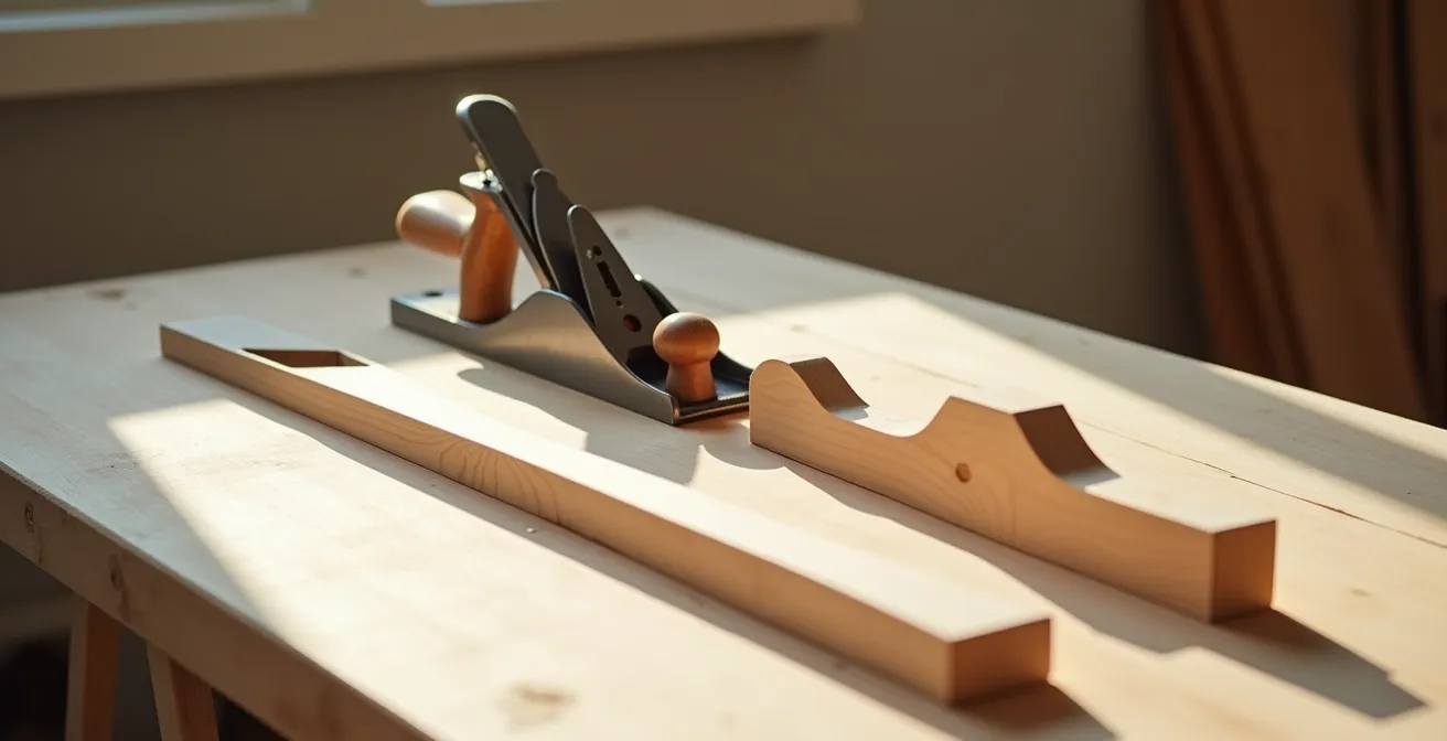
Scalpel vs Razor Plane: how to shape balsa blocks without crushing the fibers?
Shaping balsa is a process of material removal that must be executed with surgical precision to avoid compromising the wood’s internal structure. The goal is to shear the wood fibers cleanly, not to crush or tear them. A crushed cellular structure creates a weak, spongy surface that absorbs excess glue, adds weight, and provides a poor foundation for finishing. The choice and sequence of tools are therefore critical from a material science perspective.
The common mistake is using a single tool for all shaping tasks. A successful workflow involves a progression from coarse removal to fine detailing. Bulk material is best removed with a razor saw, making cuts perpendicular to the grain to establish basic outlines. Following this, a razor plane, held at a low angle (around 15 degrees), is the ideal tool for shaping curves. It acts like a micro-tome, slicing off thin layers of wood without compressing the cells underneath. The final details should be carved with a scalpel, ideally one with a chisel-ground edge, which provides more control than a standard double-beveled blade.
The most critical factor in this process is always working in the direction of the “rising” grain. You must read the grain of the wood and cut “downhill” to prevent tear-out. This requires examining the side of the wood block to see the direction of the fibers. Using a sharp blade is a given, but true mastery comes from understanding that you are performing micro-surgery on a fibrous composite matrix. Each cut should be a deliberate shearing action, preserving the integrity of the material you are leaving behind.
- Stage 1: Use a razor saw for bulk material removal (cuts perpendicular to grain).
- Stage 2: Switch to a razor plane for shaping curves (15-degree blade angle).
- Stage 3: Apply a scalpel with a chisel-ground edge for detail work.
- Stage 4: Finish with progressive sanding blocks (120, 240, 400 grit sequence).
- Critical tip: Always work in the direction of rising grain to prevent tear-out.
The charred edge problem: how laser cutting changes glue adhesion
Laser-cut kits offer incredible precision, but they introduce a significant material science challenge: the charred edge. This blackened surface is not just soot; it is a pyrolysis zone, or Heat-Affected Zone (HAZ), where the balsa wood has been thermally decomposed. The cellulose and lignin have been converted into a carbonaceous char, a material with fundamentally different properties from the parent wood. This char is brittle, porous, and, most importantly, it does not bond well with common modeling adhesives.
The extent of this charring is a direct function of the laser’s parameters. Research shows that to minimize char, laser cutting at speeds faster than 10mm/second is optimal, as it reduces the dwell time of the beam and thus the thermal input into the wood. Slower speeds create a deeper, more glass-like char that is almost impossible for adhesives to penetrate. Attempting to glue directly onto a heavily charred edge is like trying to glue two pieces of charcoal together; the bond will be to the weak char layer, not the strong wood underneath, resulting in a joint that can fail at a fraction of its potential strength.
The choice of adhesive becomes paramount when dealing with laser-cut parts. A light sanding to remove the worst of the char is always recommended, but the type of glue used can make a significant difference in salvaging bond strength, as shown by comparative adhesion data.
| Adhesive Type | Bond Strength (Clean Edge) | Bond Strength (Light Char) | Bond Strength (Heavy Char) | Char Tolerance |
|---|---|---|---|---|
| Cyanoacrylate (CA) | 100% | 65% | 30% | Poor |
| Aliphatic Resin | 100% | 75% | 45% | Moderate |
| Epoxy (30-min) | 100% | 85% | 60% | Good |
| Polyurethane | 100% | 80% | 55% | Moderate |
As the data clearly indicates, thin, fast-curing adhesives like Cyanoacrylate (CA) perform very poorly on charred surfaces, losing up to 70% of their strength. Their low viscosity and rapid cure time prevent them from penetrating the char to reach the solid wood. Slower-curing, gap-filling glues like 30-minute epoxy show the best performance. Their longer working time allows them to seep into the porous char and create a mechanical lock, while their viscosity helps bridge the irregular surface. From an engineering standpoint, when building a laser-cut kit, switching to epoxy for critical structural joints is a necessary adaptation to overcome the material changes induced by the cutting process.
How to pin balsa parts without splitting the wood grain?
Pinning parts to a building board is a standard assembly step, but it is also a moment of high risk. Forcing a pin into balsa wood, especially dense or C-grain sheets, creates a wedge effect that can easily split the delicate grain structure. Each split acts as a stress concentrator, a point from which a crack can propagate under flight loads, leading to catastrophic failure. The solution is to transform the action from a brute-force insertion into a controlled process that respects the material’s fiber structure.
The most effective method is the pilot hole technique. By using a tool like a hypodermic needle—which is hollow and sharp—you can cut a clean pilot hole that is slightly smaller than the pin’s diameter. This removes a core of wood fibers instead of displacing them, eliminating the stress that causes splitting. The technique requires precision: marking pin locations to avoid running parallel to a single grain line, angling the hole slightly to the grain, and using a small piece of masking tape at the entry point to prevent surface tear-out. The pin is then inserted with a slow, twisting motion, allowing it to “cross-stitch” the fibers rather than splitting them apart.

For builders working with exceptionally light and fragile contest-grade balsa, or for those who want to eliminate the risk of splitting entirely, there are alternative engineering solutions that bypass the need for pins altogether.
Case Study: Magnetic Building Board Alternative to Pinning
To solve the splitting problem, Easy Built Models pioneered a pinless assembly system. Their method uses a steel-backed building board and powerful rare-earth magnets to hold parts in place. This innovative approach completely eliminates the risk of splitting, which is especially beneficial when working with ultra-light contest-grade balsa below 6 lb/cu.ft density. The magnetic system holds parts with just enough force for gluing operations while allowing for infinite and precise repositioning, representing a true engineering solution to a common construction problem.
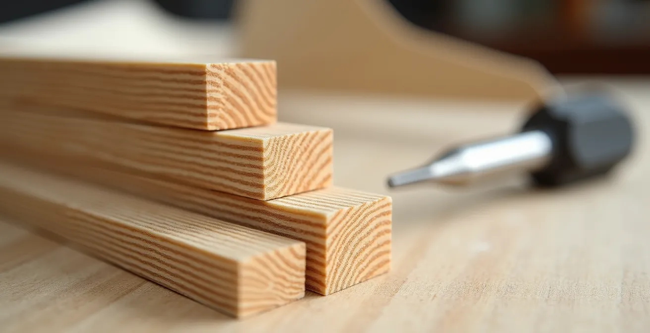
How to select “contest grade” balsa to shave grams off your airframe?
The term “contest grade” is often used, but what does it mean from an engineering perspective? It refers to balsa wood at the lowest end of the density spectrum, officially specified as being in the 4-7 lb/cu.ft range. Selecting wood in this category is the first step in building a “floater,” but relying solely on a supplier’s label is a mistake. Balsa is a natural product with significant density variations, even within the same sheet. The dedicated builder must become a quality control engineer, measuring and verifying the density of every piece of wood destined for a competitive airframe.
The cost for this premium material can be substantial, with some specialty suppliers charging a 100% price increase or more for hand-selected, density-verified sheets. For builders on a budget or those needing to verify their own stock, a simple DIY density measurement using the water displacement method provides accurate, empirical data. This scientific approach removes all guesswork from the selection process.
Here is the procedure to calculate density precisely:
- Weigh the balsa sheet on a digital gram scale and record the weight (in grams).
- Fill a graduated cylinder or a container of known volume with water, noting the initial volume.
- Fully submerge the balsa, using a thin wire to hold it under the surface.
- Record the new water level. The difference between the new and initial levels is the volume of the balsa sheet in cubic centimeters (cc), as 1 ml of displaced water equals 1 cc of volume.
- Calculate the density using the formula: Density (lb/cu.ft) = [Weight (g) / Volume (cc)] x 62.4.
By performing this test, you can categorize your entire wood stock. Any wood over 8 lb/cu.ft should be reserved for non-flying parts or structural reinforcement, while sheets in the 4-7 lb/cu.ft range are tagged for flight-critical components like ribs, tail surfaces, and fuselage sheeting. This methodical process ensures that every gram on your airframe is justified by its structural contribution.
How to Transition from Static Modeling to RC Flying Without Crashing Your First Build?
Transitioning from static models to Radio Control flight introduces a new, unforgiving force: kinetic energy. A static model only needs to support its own weight. A flying model must endure flight loads, landing stresses, and the inevitable hard arrivals. The key to survival is not just building light, but building smart, using principles of energy absorption and structural redundancy. A crash is a rapid deceleration event; a well-engineered airframe manages and dissipates that energy without catastrophic failure.
One of the most effective strategies is to abandon the idea of uniform density throughout the airframe. Instead, adopt a “crash-resilient” design philosophy that uses variable density balsa strategically. This involves using tougher, medium-density balsa (10-12 lb/cu.ft) in high-impact zones while preserving lightweight contest balsa for the protected core structure of the model.
Case Study: Crash-Resilient Design Using Variable Density Balsa
Builder Rob Reynolds’ approach to crash-proofing involves creating “ablative armor” for his models. He uses medium-density balsa for sacrificial components like leading edges, wingtips, and landing gear mounts. The core structure, including the wing spars and fuselage formers, is built from lighter wood. This design ensures that upon a hard landing, the kinetic energy is absorbed by the sacrificial parts, which may crack or deform but protect the critical, harder-to-repair core structure. This approach results in models that can survive multiple incidents with only cosmetic damage that is easily repaired at the field.
Before any flight, a rigorous structural integrity check is non-negotiable. This is not a casual glance but a systematic, hands-on inspection to identify potential failure points before they are exposed to flight stresses. A loose glue joint or a micro-crack can quickly propagate into a major in-flight failure. This pre-flight audit is your last line of defense against a preventable crash.
Your pre-flight structural integrity audit:
- Wing Torsion Test: Gently twist the wing panels in opposite directions. Listen for any creaking or popping sounds that indicate a failing glue joint in the wing structure or at the root.
- Control Surface Check: Wiggle all control surfaces (ailerons, elevator, rudder). There should be zero play or looseness in the hinges; secure any that feel sloppy.
- Structural Mount Inspection: Firmly press on the firewall and inspect the landing gear attachment points. The structure should feel solid, with no detectable flex or visible stress cracks in the surrounding wood.
- Center of Gravity Verification: Confirm the model’s Center of Gravity (CG) is within the plan’s specified range, typically 25-30% of the wing’s mean aerodynamic chord. An incorrect CG is a primary cause of instability.
- Control Linkage Pull Test: Perform a firm pull test on all servo-to-control-surface linkages. Each linkage should withstand a minimum of 2 lbs of force without deflecting or separating.
How to Start Building Static Aircraft Models Without Spending Over $100?
Before we discuss the advanced balancing techniques for an RC model, it’s crucial to master the fundamentals of material handling and tool use. A common misconception is that starting this hobby requires a significant financial investment. In reality, the core principles of balsa construction can be learned with a minimal, cost-effective toolkit. This “minimum viable” approach not only saves money but forces a focus on technique and a deeper understanding of the material itself.
The beauty of balsa is its workability with simple hand tools. You do not need a workshop full of power equipment. A sharp blade, a straight edge, and a flat surface are the foundations of the entire craft. In fact, building from basic balsa sheets and sticks, rather than expensive pre-fabricated kits, provides a significant economic advantage. Sourcing materials from a craft store instead of a hobby-specific shop can result in a 70% cost reduction for the raw materials of a given project. This approach also hones essential skills like reading plans and cutting accurate parts, skills that are often bypassed when using laser-cut kits.
The initial investment should be focused on a small set of high-quality tools that will last for years. A cheap, dull knife or a flimsy ruler will only lead to frustration and poorly fitting parts. Here is the essential toolkit that will allow you to tackle a wide range of static model plans for under $100:
- #11 X-acto knife with a 100-pack of replacement blades ($15): A sharp blade is the single most important tool. Change blades at the first sign of dullness.
- 18-inch steel ruler with a cork backing ($12): Essential for straight cuts. The cork backing prevents slipping.
- Self-healing cutting mat (minimum 12×18 inches) ($20): Protects your work surface and the life of your blades.
- Sanding block with assorted grit papers (120, 240, 400) ($10): For shaping and finishing parts.
- Titebond II wood glue (4 oz bottle) ($8): A strong, sandable, and non-toxic aliphatic resin perfect for balsa.
- Bonus: Leather strop ($15): A few passes on a strop can restore a razor edge to a slightly dull blade, extending its life tenfold.
With this simple toolkit, a builder can develop the fundamental tactile skills—feeling the blade slice through fibers, learning the pressure needed for a perfect cut—that are the true foundation of quality construction, whether for a static display piece or a high-performance RC aircraft.
Key takeaways
- Balsa’s performance is dictated by its anisotropic properties; strength and stiffness are not uniform in all directions.
- Grain orientation (A, B, or C-grain) is a critical engineering choice that affects a component’s ability to handle specific loads (flex vs. compression).
- Every construction process (cutting, sanding, gluing) is a material science interaction that can either preserve or destroy the wood’s inherent structural integrity.
How to Transition from Static Modeling to RC Flying Without Crashing Your First Build?
Having established the principles of structural integrity and fundamental building skills, we can now address the second critical aspect of the transition to RC: the physics of balance. An airplane that is structurally sound but improperly balanced is destined to crash. The Center of Gravity (CG) is the single most important parameter for flight stability. A model that is too nose-heavy will be sluggish and require excessive speed to fly, while a tail-heavy model will be wildly unstable and virtually uncontrollable.
The common approach is to complete the build and then add lead weights to the nose or tail to achieve the correct balance. From a performance engineering standpoint, this is a cardinal sin. Adding “dead weight” negates all the hard work of selecting lightweight balsa. It is an admission of defeat. The advanced builder achieves the correct CG naturally through the strategic selection and placement of materials during construction. This technique, known as density mapping, treats the entire airframe as a single integrated system to be balanced.
Case Study: Natural CG Achievement Through Wood Density Selection
Advanced scale builders have perfected the technique of achieving a perfect CG without ballast. This involves creating a density map of the aircraft before construction begins. The principle is simple: use heavy-density balsa (12-14 lb/cu.ft) for components aft of the CG, such as tail surfaces and the rear fuselage. Use medium-density wood (8-10 lb/cu.ft) for the central fuselage, and reserve the lightest, ultra-light contest-grade balsa (4-6 lb/cu.ft) for all components forward of the CG, including the nose, firewall, and cowling. This methodical placement of mass can entirely eliminate the 20-30 grams of lead ballast typically required for balance on a medium-sized model.
This principle of leverage is eloquently summarized by a veteran of RC forums. As RC builder Mark Shuman states, the effect of weight is magnified by its distance from the CG.
Saving 1 gram in the tail is equivalent to saving 3-4 grams in the nose – this principle should dictate every single wood choice aft of the CG.
– Mark Shuman, RCU Forums
This quote encapsulates the entire philosophy. Every piece of wood selected for the tail assembly should be the densest, strongest piece you have, while every piece for the nose should be the absolute lightest. By thinking about balance from the very first piece of wood you cut, you engineer a lighter, more efficient, and better-performing aircraft.
Now, apply these engineering principles to your next build. Approach your wood rack not as a craftsman looking for a piece that fits, but as a material scientist selecting a component with specific engineering properties. Select your next piece of balsa with purpose and watch your model’s performance transform.