Frustrated by missing or inaccurate model kit parts? This guide shows you how to take control by designing your own pieces in CAD. It’s not about becoming an engineer; it’s about adopting a ‘digital craftsman’s’ mindset, using simple tools to measure, design, and prepare parts for 3D printing, while avoiding common rookie mistakes that can ruin your work.
There’s a moment every scale modeler dreads: opening a prized kit only to find a critical part is broken, warped, or worse, completely missing. For decades, the solutions were limited to the painstaking art of scratch-building with styrene sheets or the often-fruitless hunt for rare aftermarket resin sets. The world of Computer-Aided Design (CAD) seemed a distant, unapproachable realm, reserved for engineers with years of training and complex, expensive software. The barrier to entry felt insurmountably high, leaving hobbyists to make do with less-than-perfect fixes.
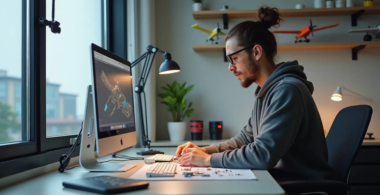
But what if the key to unlocking flawless custom parts wasn’t about mastering complex engineering principles, but about adopting a new mindset? This guide is built on that premise. We’ll explore the idea of digital craftsmanship, an approach that treats CAD not as an engineering discipline, but as a natural extension of the modeler’s workbench. It’s about translating your hands-on skills into the digital space to create precisely what you need. This is not a formal course in industrial design; it’s a practical roadmap for the tech-savvy modeler who wants to solve a real-world problem: creating that one perfect part that doesn’t exist anywhere else.
This article will walk you through the entire process, from choosing the right beginner-friendly software to mastering the essential skill of measuring physical parts. We will demystify the most common pitfalls that turn a perfect digital design into a failed 3D print, and finally, show you how these new skills can elevate your hobby to a level of fidelity and creativity you never thought possible.
Summary: A Modeler’s Path to Designing Custom Parts in CAD
- Fusion 360 vs TinkerCAD: which is better for designing 1:How to Start Building Static Aircraft Models Without Spending Over $100?
- How to use digital calipers to measure plastic kits for perfect 3D fit?
- The wall-thickness trap: why your CAD design falls apart when printed at 1:How to Start Building Static Aircraft Models Without Spending Over $100?
- Non-manifold edges: why your slicer creates holes in your solid fuselage design?
- Thingiverse or Cults3D: where to upload your aviation designs for the community?
- SLA vs FDM: Which 3D Printer Technology Actually Works for 1:How to Start Building Static Aircraft Models Without Spending Over $100?
- What Defines a High-Fidelity Replica for Serious Aviation Collectors?
- Why Modeling Prototype Aircraft Requires More Research Than Production Variants?
Fusion 360 vs TinkerCAD: which is better for designing 1:How to Start Building Static Aircraft Models Without Spending Over $100?
The first step into CAD can feel like choosing between a simple hammer and a complex CNC machine. On one hand, you have TinkerCAD, a browser-based tool known for its incredible accessibility. It’s the perfect entry point because it requires zero prior 3D modeling knowledge. Its ‘building block’ approach of adding and subtracting shapes is intuitive and allows you to grasp the fundamentals of working in a 3D space without being overwhelmed. For simple, geometric parts like an instrument panel box, a custom bomb pylon, or internal structural supports, TinkerCAD is not just adequate; it’s often faster and more efficient.
On the other end of the spectrum is Autodesk Fusion 360. Its parametric modeling, organic sculpting capabilities, and precise assembly tools represent a significant step up in power and complexity. The learning curve is undeniably steeper, but it unlocks the ability to create the complex, curved surfaces essential for aircraft modeling—think fuselages, wing fillets, and engine cowlings. The choice isn’t about which is “better,” but which is right for your current task and future ambitions. Many modelers adopt a powerful two-tool workflow, a practical example of digital craftsmanship.
Case Study: The TinkerCAD-to-Fusion Workflow
Many experienced modelers start projects in TinkerCAD to quickly prototype the basic shape and size of a part. Once the fundamental geometry is established, they use the native ‘Send to Fusion 360’ command. This simple action transforms the basic TinkerCAD shapes into editable objects within Fusion 360’s more powerful environment. As users have reported, this workflow makes previously impossible tasks like filleting two bodies together suddenly trivial, allowing for a smooth progression from simple block-outs to refined, organic final parts without starting from scratch.
This hybrid approach allows you to leverage the speed of TinkerCAD for initial concepts and the power of Fusion 360 for the detailed finishing work. It’s the most effective way to build your skills progressively without hitting a wall. To help you decide where to begin, consider the specific nature of your project.
Action Plan: Choosing Your First CAD Tool
- Start with TinkerCAD for blocky, geometric parts like instrument boxes and structural components.
- Use TinkerCAD’s drag-and-drop interface to learn 3D space concepts through simple projects like creating a custom base or jig.
- Progress to Fusion 360 when you need to create organic curves, lofts, or splines for wings and fuselages.
- Choose Fusion 360 immediately if your new part must fit precisely with existing, complex kit components that require parametric adjustments.
- Consider using both tools: TinkerCAD for quick prototypes and mock-ups, and Fusion 360 for final, detailed refinements.
How to use digital calipers to measure plastic kits for perfect 3D fit?
If CAD software is your digital workbench, then a good set of digital calipers is your most essential measuring tool. It is the bridge between the physical model kit on your desk and the digital design on your screen. Achieving a perfect fit for a custom part—whether it’s a replacement landing gear door or a corrected spine for a fuselage—begins with precise, accurate measurements. Eyeballing it with a ruler simply won’t cut it in a hobby where a tenth of a millimeter can make all the difference.
The beauty of digital calipers is their precision and ease of use. With most standard caliper specifications boasting 0.001 inch accuracy, you can capture dimensions with a level of confidence that is impossible with analog tools. The process is straightforward: the outside jaws measure external surfaces (like the diameter of a rocket pod), the inside jaws measure internal spaces (like the opening of a jet intake), and the depth rod measures the depth of a hole or step (like a cockpit tub). A crucial tip for modelers is to take multiple measurements of the same feature and average them to account for any slight molding imperfections in the kit part.
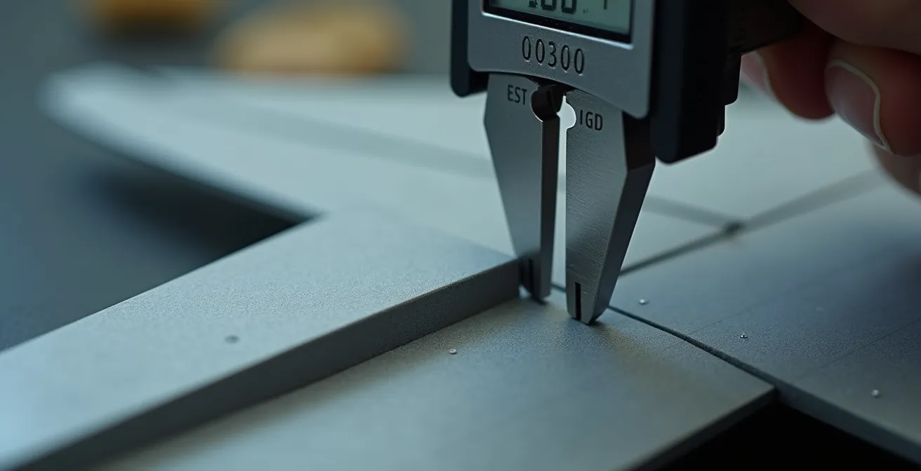
As the image above illustrates, the goal is to get a clean, firm contact with the part without compressing the plastic. Remember, you aren’t just measuring the part you’re replacing; you are measuring the space it needs to fit into. This is a key principle of functional design. Always add a small tolerance to your digital design—typically around 0.1mm to 0.2mm—to account for the 3D printing process. This “wiggle room” ensures your perfectly measured part will actually slot into place rather than being an impossibly tight fit. This practice transforms your design from a mere copy into a functional, improved component.
The wall-thickness trap: why your CAD design falls apart when printed at 1:How to Start Building Static Aircraft Models Without Spending Over $100?
You’ve spent hours crafting a beautiful, detailed part in your CAD software. On the screen, it looks solid, robust, and perfect. You send it to your 3D printer, wait with anticipation, and end up with a crumpled, fragile mess or nothing at all. Welcome to the wall-thickness trap, arguably the most common and frustrating pitfall for modelers entering the world of digital design. What looks substantial on a 24-inch monitor can become impossibly thin when scaled down to 1:72 or 1:48.
The problem lies in the disconnect between the design environment and the physical reality of 3D printing. A fuselage wall that you design to be 2mm thick in your CAD program seems perfectly reasonable. However, when you scale that entire model down to 1:72, that wall becomes just 0.027mm thick—far thinner than a human hair and utterly unprintable by any consumer-grade technology. Every 3D printer, whether it’s FDM (filament) or SLA (resin), has a minimum feature size and wall thickness it can reliably produce. For most SLA printers, this is around 0.3mm to 0.5mm. Anything thinner will likely fail to form, warp during printing, or crumble during post-processing.
To avoid this trap, you must adopt a “scale-first” mindset. Before you design anything, know the minimum wall thickness your printer and material can handle. Then, design your parts with that constraint in mind. This might mean making some parts non-prototypically thick. For example, the edges of a landing gear door or the walls of a cockpit might need to be designed at a thickness of 0.5mm, even if that’s technically out of scale. The goal is a successful, usable part, not a theoretically perfect but physically impossible one. This is a core tenet of digital craftsmanship: balancing accuracy with the practical limitations of the manufacturing process.
Non-manifold edges: why your slicer creates holes in your solid fuselage design?
If the wall-thickness trap is the most common physical pitfall in 3D design, then its digital counterpart is the dreaded non-manifold edge. This highly technical-sounding term describes a very simple problem: your 3D model is not “watertight.” Imagine your digital fuselage is a bucket. If there’s even a microscopic hole in it, the water will leak out. In the world of 3D printing, the “slicer”—the software that converts your 3D model into printable layers—is the water. When it encounters a hole, it gets confused. It doesn’t know what’s “inside” versus “outside” the model, which can lead to bizarre printing errors, missing layers, or gaping holes in your final part.
Where do these errors come from? They often occur when you join or subtract shapes in your CAD program. For instance, if you’re attaching a wing to a fuselage, the surfaces where they meet must be perfectly merged. If there’s an infinitesimal gap or an overlapping internal face, you’ve created a non-manifold error. Another common cause is an edge that is shared by more than two faces. In the real world, an edge (like the spine of a book) can only have two sides. If your digital model has an edge with three or more faces connected to it, it represents a physically impossible geometry that the slicer cannot interpret.
Most modern CAD programs, including Fusion 360, have built-in tools to check for and repair these issues. Slicer software like Cura or Lychee Slicer also often flags these errors before you start a print. The key is to not ignore the warnings. Learning to identify and fix these small geometric flaws is a crucial skill. It’s the digital equivalent of filling and sanding a seam on a plastic model. A clean, watertight digital model is the foundation of a successful print. Skipping this step is a recipe for frustration and wasted material, so developing a habit of checking your model’s integrity before every export is essential for consistent results.
Thingiverse or Cults3D: where to upload your aviation designs for the community?
Once you’ve successfully designed and printed your first few custom parts, you’ll likely feel a sense of pride and a desire to share your work. The spirit of digital craftsmanship extends beyond your own workbench and into the global community of modelers. Two of the most popular platforms for sharing 3D designs are Thingiverse and Cults3D, and choosing between them depends on your goals as a creator.
Thingiverse is the original and largest repository of 3D printable files. It’s owned by MakerBot and operates on a purely free, open-source ethos. Uploading your design here means contributing to a vast public library, making your work accessible to the maximum number of people. It’s an excellent platform for building a reputation and getting feedback from a wide audience. The downside is that its sheer size can make it difficult for your designs to stand out, and the site has been known to suffer from performance issues. It’s the digital equivalent of a massive, bustling public park.
Cults3D, on the other hand, operates more like a curated marketplace or a boutique gallery. While it also hosts a large number of free designs, it is best known for providing a platform for designers to sell their files. The user interface is generally slicker, and the community is often perceived as being more focused on high-quality, polished designs. If you’ve spent dozens of hours creating a highly detailed and accurate set of correction parts, Cults3D gives you the option to monetize that effort. This can be a great way to fund your hobby and incentivizes the creation of more complex and niche designs that serve the serious modeler.
Your choice depends on your motivation. Do you want to share freely with the largest possible community and contribute to a public good? Thingiverse is your answer. Do you want to present your work in a more curated environment and potentially earn money from your high-effort designs? Cults3D is likely the better fit. Many designers even use both, offering simpler parts for free on Thingiverse to drive traffic to their premium files on Cults3D.
SLA vs FDM: Which 3D Printer Technology Actually Works for 1:How to Start Building Static Aircraft Models Without Spending Over $100?
Choosing your design software is only half the battle; bringing that design into the physical world requires a 3D printer, and the two dominant technologies for hobbyists—SLA and FDM—offer vastly different results. The right choice depends entirely on the function and scale of the part you are creating. This is a critical decision in your measurement-to-model workflow, as the technology you use directly impacts design constraints like wall thickness.
FDM (Fused Deposition Modeling) is the most common and affordable type of 3D printing. It works by extruding a thin filament of molten plastic (like PLA or ABS) layer by layer. Its main advantages are its low cost, large build volumes, and the strength of the printed parts. For a modeler, FDM is ideal for creating larger, structural components. Think of things like custom display stands, internal wing spars for a large-scale model, or robust jigs to hold fuselage halves in alignment while the glue sets. However, FDM’s major drawback is its resolution. The layering process often leaves visible lines on the surface, which require significant sanding and filling to achieve a smooth finish suitable for painting. It struggles to reproduce the very fine details required for small-scale modeling.
SLA (Stereolithography), on the other hand, is the king of detail. This technology uses a UV laser or projector to cure liquid resin layer by layer into a solid object. SLA printers can produce parts with incredible surface smoothness and capture microscopic details, making them the go-to choice for serious modelers. Tiny cockpit instrument panels, delicate antennas, finely detailed landing gear, and gun barrels are all perfect applications for SLA. The trade-off is a smaller build volume, the mess and fumes associated with handling liquid resin, and parts that can be more brittle than their FDM counterparts. However, for achieving a level of detail that rivals or even surpasses injection-molded kits, SLA is unparalleled.
What Defines a High-Fidelity Replica for Serious Aviation Collectors?
For a casual builder, a finished model is a pleasing representation of an aircraft. For a serious aviation collector, however, the goal is a high-fidelity replica—a miniature that captures not just the general shape, but the precise details, quirks, and accuracy of the real-world subject. This pursuit of fidelity is where the skills of digital craftsmanship become truly transformative, allowing a modeler to move beyond the limitations of what’s provided in the box.
A high-fidelity replica is defined by several key characteristics. First is dimensional accuracy. This means the model’s length, wingspan, and the placement of key features like control surfaces and windows are correct according to historical blueprints, not just the kit manufacturer’s interpretation. Using digital calipers and CAD, a modeler can check the kit’s accuracy and, if necessary, design and print correction parts, such as a properly shaped nose cone or a correctly sized tail fin. Second is configurational accuracy. An aircraft often has many variants, with different engine cowlings, antenna fits, or cockpit layouts. A serious collector will ensure their model represents a specific aircraft at a specific point in time. CAD allows you to design and print these variant-specific parts that are often omitted from mass-produced kits.
Finally, high fidelity is about detail density. This includes the fine details that bring a model to life: the intricate structure of a landing gear bay, the precise layout of a cockpit, or the delicate framing of a canopy. While photo-etched metal parts have traditionally been the solution for this, SLA 3D printing now allows for the creation of fully three-dimensional, highly detailed components that were previously impossible for a hobbyist to make. By learning to design these parts, you are no longer a passive assembler of a manufacturer’s product; you become an active researcher and creator, elevating the kit into a true museum-quality piece.
Key Takeaways
- Embrace a “digital craftsman” mindset: CAD is an extension of your workbench, not a separate engineering field.
- Your measurement-to-model workflow is critical; precise digital calipers are the bridge between your physical kit and your digital design.
- Always design with your final print scale and printer technology in mind to avoid common “printability traps” like insufficient wall thickness and non-manifold geometry.
Why Modeling Prototype Aircraft Requires More Research Than Production Variants?
Building a model of a production aircraft like a P-51D Mustang or a Spitfire Mk.IX is a process of replication. There are thousands of photos, dozens of surviving examples, and extensive documentation to guide you. The standard is known, and the goal is to match it. Modeling a prototype aircraft, however, is an entirely different challenge. It’s an act of historical investigation and reconstruction, and it is here that your digital design skills become an indispensable research tool.
Prototypes, such as the YF-12 or the Hawker P.1121, often existed in a state of constant flux. They were modified weekly, sometimes daily, with different canopy shapes, wing roots, or engine intakes. The documentation is often sparse, contradictory, or consists of little more than a few grainy black-and-white photos and some preliminary manufacturer’s drawings. This is where a modeler becomes a detective. Your task is not just to build a kit, but to determine what the aircraft *actually* looked like on a specific day of its test life. This requires far more research, cross-referencing different sources, and making educated inferences.
CAD software becomes your digital investigation board. You can import a schematic, overlay a photograph, and trace the true shape of a fuselage spine that was changed after the initial drawings. You can model a hypothetical air scoop based on a blurry close-up and see if it fits the known contours of the aircraft. It allows you to test theories. Did they use the landing gear from a Hunter? You can download a 3D model of Hunter gear and digitally test-fit it to your prototype’s fuselage. This process moves beyond simple part design and into the realm of digital archeology. It allows you to create a model of an aircraft that may have never been kitted and whose true form is a puzzle waiting to be solved. This is the ultimate expression of digital craftsmanship: not just correcting a kit, but creating a definitive physical record from scattered historical clues.
Now that you understand the principles, the path is clear. Start with a simple project, like a replacement antenna or a small interior box. Get comfortable with the measure-design-print workflow. Your journey into digital craftsmanship has just begun, and the only limit is your imagination.