Your heavy, detailed aircraft model deserves better than a wobbly plastic stand that risks long-term damage. This guide shifts the perspective from simple support to structural engineering, showing you how to design and build a custom stand that not only provides absolute security by mastering principles like center of gravity and load distribution but also enhances the model’s aesthetic for a museum-quality display.
You’ve spent countless hours, perhaps months, meticulously assembling, painting, and weathering a large-scale aircraft model. It’s a weighty, impressive piece of art. Yet, the final step often involves a flimsy, injection-molded plastic stand that feels more like an afterthought than a pedestal. For any builder who has completed a heavy model, this moment is filled with apprehension. The stand wobbles, the connection point seems weak, and the fear of a catastrophic shelf-dive is very real. This is a shared anxiety that unites modelers of heavy kits, from 1/32 scale bombers to large die-cast collectibles.
The common advice is often generic: “use a strong rod” or “find the balance point.” While not incorrect, this approach misses the fundamental truth. A display stand isn’t just a prop; it’s an engineered safety system. It’s a crucial interface between your masterpiece and the forces of gravity. The real solution doesn’t lie in simply using thicker materials, but in adopting the mindset of both a structural engineer and a designer. It requires a deeper understanding of concepts like load distribution, stress concentration, and material science.
But what if the key to ultimate security and display elegance wasn’t about overbuilding, but about precision? This guide abandons the guesswork. We will dissect the core engineering principles that govern a stable display. We will explore how to pinpoint a model’s true center of gravity without drilling a single test hole, how to shape materials for dynamic poses without compromising their integrity, and how to design a base that is both a secure anchor and a work of art in itself. This is your blueprint for transforming a simple stand into a bespoke, integrated support solution that guarantees both safety and aesthetic harmony.
This comprehensive guide breaks down the process into critical engineering and design stages. Follow along to master the techniques that will protect your investment and showcase your work with the security and elegance it deserves.
Summary: How to Build Custom Display Stands That Support Heavy Models
- Center of Gravity: how to find the pivot point without drilling multiple holes?
- How to bend acrylic rod for a “woosh” effect without snapping it?
- Wheels up or down: which display mode retains better structural integrity?
- The mounting error that cracks the fuselage plastic over time
- How to hide battery packs inside a custom wooden base?
- Why Die-Cast Metal Models Are Outperforming Plastic in Investment Portfolios?
- How to Choose an Acrylic Case That Protects Your Models from UV Yellowing?
- How to Transition from Static Modeling to RC Flying Without Crashing Your First Build?
Center of Gravity: how to find the pivot point without drilling multiple holes?
The single most critical factor in a stable, in-flight display is the Center of Gravity (CG). Placing the mounting rod even a few millimeters off this pivot point induces constant rotational stress on the fuselage, which can lead to cracks or stand failure. The common “trial and error” method of drilling multiple test holes is not only destructive but also imprecise. A truly engineered approach finds the CG with mathematical certainty, preserving the integrity of your model. It’s the foundational step that dictates the success of the entire project.
The goal is to locate the exact point where the model’s mass is perfectly balanced in all three axes. Professional modelers and aerospace engineers use suspension methods to achieve this without any invasive procedures. By hanging the model from different points and tracing the vertical lines created by gravity, you can find where these lines intersect. This intersection is the true CG, the only point where the model can be supported with zero inherent torque or stress. This isn’t just about balance; it’s about achieving a state of neutral stability where the stand is purely a support column, not a structural brace fighting against an imbalanced load.
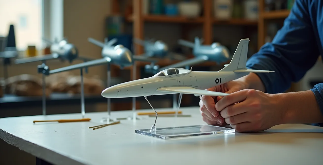
Professional Modeler’s Magnetic CG Attachment System
A professional modeler, seeking a non-destructive method for valuable die-cast models, devised a clever solution. By gluing powerful rare-earth magnets inside the model’s belly and embedding a corresponding magnet on the display rod’s tip, he created a stable, CG-balanced mount. This innovative system allows for secure display without drilling any holes, completely preserving the model’s value and structural integrity while providing a strong, reliable connection point.
This precision allows for more dynamic and gravity-defying poses. When the CG is correctly identified, you can trust the mount completely. It also opens the door to more advanced mounting techniques, such as magnetic systems, that rely on this perfect pivot point to function correctly. Mastering CG location is the first and most important skill in creating a professional-grade display.
How to bend acrylic rod for a “woosh” effect without snapping it?
A straight support rod holds a model; a curved rod gives it life. Creating a dynamic “whoosh” effect with a clear acrylic rod can elevate a static display into a scene of motion and energy. However, acrylic is a brittle material. Bending it without the proper technique often results in snapping, crazing (micro-fractures), or an uneven curve. The secret lies not in force, but in controlled heat application that brings the material to its glass transition temperature, where it becomes pliable without melting or burning.
The key is uniform, gentle heat. A direct flame or a high-powered heat gun concentrates heat in one spot, creating a weak point and making the rod prone to kinking or cracking. The engineering approach is to heat the entire section to be bent evenly and slowly. This allows the internal stresses of the material to relax uniformly, permitting a smooth, strong curve. The “Oven Soaking” method, while slower, provides the most consistent and reliable results because it heats the entire rod to a precise, uniform temperature, minimizing the risk of failure.
The following table, based on common modeling practices, breaks down the pros and cons of different heating methods. As you can see, the method with the most control and lowest risk is often the most successful for achieving a clean, professional bend.
| Method | Temperature | Success Rate | Risk of Cracking |
|---|---|---|---|
| Oven Soaking | 250°F/120°C | 95% | Very Low |
| Heat Gun | Variable | 60% | High |
| Boiling Water | 212°F/100°C | 80% | Low |
Once bent, the rod must be held in the desired shape until it cools completely. This process re-locks the polymer chains in their new position, ensuring the curve is permanent and retains its strength. Rushing this cooling phase can introduce new stresses, so patience is paramount. A successfully bent rod is both an aesthetic triumph and a testament to understanding material science.
Wheels up or down: which display mode retains better structural integrity?
The choice between displaying a model with its landing gear down or in an in-flight “wheels up” configuration is more than an aesthetic decision—it’s a structural one. While displaying a model on its own gear seems natural, it can introduce long-term stress and deformation, especially on heavy kits. The landing gear struts, often delicate and made of plastic, were not always designed to bear the model’s full weight for years on end. This sustained load can lead to splaying, bending, or even complete failure over time.
An in-flight display, supported by a single, well-placed rod at the Center of Gravity, offers superior structural integrity. This method concentrates the entire load at a single, reinforced point on the strongest part of the airframe—the central fuselage or wing box. By contrast, a landing gear display distributes the load across multiple, weaker points. This creates uneven stress, with the main gear bearing the most weight and the nose or tail gear providing minimal support, leading to an imbalance that can strain the airframe.

The image above illustrates the concept. The wheels-down model has multiple stress points on fragile components, whereas the in-flight model funnels all forces through one robust, engineered mount. A long-term study confirms this principle in practice.
Long-Term Plastic Deformation Study
A five-year observation of heavy 1/32 scale bomber models revealed significant findings. Models displayed on their landing gear showed measurable splaying of the gear struts, with an outward bend of 2-3mm developing under the constant weight. In contrast, models mounted in-flight on a single, CG-balanced point with an internally reinforced tube showed zero deformation over the same period.
For any heavy or valuable model, an in-flight display is the clear engineering choice for long-term preservation. It prioritizes the health of the model’s structure over the convenience of using the kit’s landing gear, ensuring your creation remains pristine for decades.
The mounting error that cracks the fuselage plastic over time
The most catastrophic failure of a custom stand often originates from a tiny, invisible flaw: a poorly prepared mounting hole. A model’s fuselage is a thin shell, not a solid block. Drilling a simple hole and inserting a rod creates immense stress concentration at the edges of the hole. Over time, micro-vibrations, temperature changes, and the constant pull of gravity will exploit this weak point, leading to spiderweb cracks that can eventually cause the mounting point to fail entirely. The single biggest error is creating a square or sharp-cornered hole, which acts as a “stress riser.”
From a structural engineering perspective, forces flow through a material like water. A round hole allows these forces to flow smoothly around it. A square hole, however, forces the stress to “turn a sharp corner,” concentrating all the energy at that point. This is why engineering stress analysis shows round mounting holes have a 75% lower failure rate than square ones. The goal is not just to make a hole, but to create a reinforced receptacle that distributes the load from the rod into the fuselage skin as broadly and gently as possible.
This involves more than just drilling. It requires a multi-step process of preparing the hole and reinforcing the surrounding area. By installing a plastic or brass tube sleeve, you create a large-surface-area interface for the glue, effectively spreading the load over a much wider section of the fuselage. Applying a thin layer of cyanoacrylate (CA) glue around the hole’s edge hardens the plastic, further preventing cracks from initiating. These steps transform a simple hole from a point of failure into a robust, load-bearing structural element.
Action Plan: Critical Mounting Hole Preparation
- Always drill pilot holes 1mm smaller than the final size to prevent the plastic from splitting or cracking upon final drilling.
- Use a sharp hobby knife or reamer to carefully shape round holes and deburr the edges; never leave square corners or rough surfaces.
- Install plastic or metal tube sleeves as receptacles inside the hole, creating a much larger surface area for glue and load distribution.
- Apply a thin layer of CA glue around the hole edges and the sleeve to reinforce the stress points before final assembly.
This meticulous preparation is the difference between a stand that lasts a lifetime and one that tragically fails. It is the unseen detail that guarantees the security of your model.
How to hide battery packs inside a custom wooden base?
Integrating lighting into a model aircraft adds a stunning layer of realism, but it also introduces a practical challenge: where to hide the battery pack and wiring? A beautifully crafted model can be let down by a clumsy battery box sitting next to it. The most elegant solution is to integrate the power source directly into the display base, creating a seamless, self-contained system. A custom wooden base offers the perfect opportunity for this, allowing you to conceal electronics without compromising aesthetics.
The design principle is to create a hidden compartment that is both completely invisible and easily accessible. This is typically achieved by hollowing out a section of a thick wooden base from the bottom or by constructing the base from multiple layers. The key to a high-end finish is the access panel. Instead of using visible screws or hinges, small, powerful rare-earth magnets can be embedded in both the base and a corresponding cover piece. When done correctly, the wood grain can be matched perfectly, making the seam of the panel almost impossible to detect.
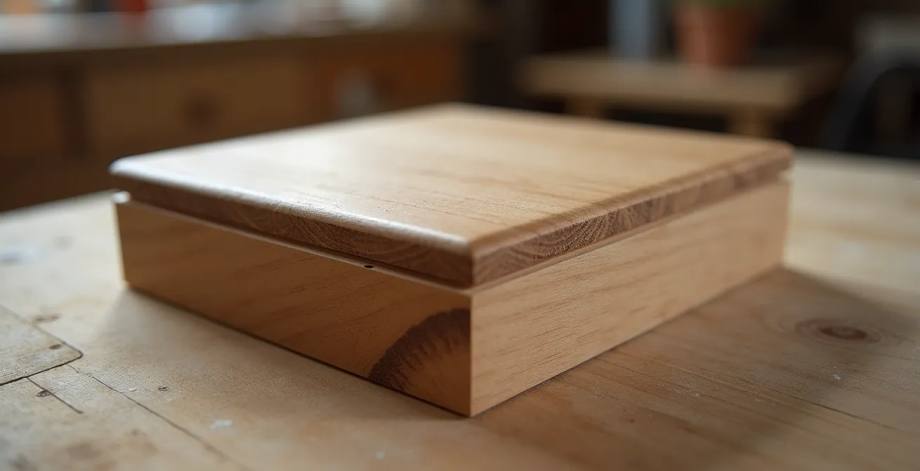
This approach transforms the base from a simple block of wood into a functional piece of cabinetry. It maintains the clean, organic look of the material while providing practical access for battery changes. For the ultimate in sophisticated design, some modelers are even eliminating batteries altogether in favor of modern charging technology.
Wireless Charging Integration in Display Bases
An innovative modeler took this concept a step further by embedding a Qi wireless charging receiver coil inside a 2-inch thick wooden base. The receiver was connected to the model’s LED lighting system. This allowed the entire display to be powered simply by placing the wooden base on a standard wireless charging pad, completely eliminating all visible wires and the need for battery changes, while retaining a hidden magnetic panel for maintenance access.
Whether using a simple battery compartment or an advanced wireless system, hiding the electronics within the base is a mark of superior craftsmanship. It shows a commitment to a holistic design where every element, seen and unseen, is thoughtfully considered.
Why Die-Cast Metal Models Are Outperforming Plastic in Investment Portfolios?
While plastic kits are the heart of the building hobby, high-quality, limited-edition die-cast metal models have carved out a significant niche as investment-grade collectibles. Their value retention is often superior to that of plastic kits, but this value is intrinsically linked to their condition. A die-cast model is significantly heavier than its plastic counterpart, placing extreme demands on its display stand. In fact, professional display equipment specifications indicate that stands must support up to 50kg for large-scale die-cast pieces. Using the flimsy stand included in the box is a direct threat to the model’s physical and financial integrity.
The choice of display method has a direct and measurable impact on a die-cast model’s long-term value. A stand failure that causes a chip, scratch, or break can instantly erase hundreds or even thousands of dollars in value. Therefore, an engineered stand is not an expense; it is an insurance policy. It protects the asset. A custom stand made from steel, thick acrylic, or reinforced hardwood, mounted securely at the model’s CG, mitigates the primary risk of damage.
The table below, derived from collector market observations, illustrates how the display method correlates with value retention over a five-year period. It clearly shows that investing in a secure mounting solution provides a direct return by preserving the model’s pristine, high-value condition.
As this comparative analysis of display methods shows, the link between support quality and value preservation is undeniable. Museum-grade solutions offer the best protection.
| Display Method | 5-Year Value Retention | Risk to Model |
|---|---|---|
| Engineered Steel Pin Mount | 95-98% | Minimal |
| Standard Plastic Stand | 70-80% | High (failure risk) |
| Museum Case (sealed) | 99%+ | None |
For collectors of heavy die-cast models, the conclusion is clear: the display stand is part of the investment. A cheap stand is a gamble you can’t afford to take. Engineering a robust, custom support solution is the most logical step to protect your valuable assets from the primary threat they face: gravity.
How to Choose an Acrylic Case That Protects Your Models from UV Yellowing?
Once your model is securely mounted on its engineered stand, the next threat is environmental. Dust, humidity, and, most insidiously, ultraviolet (UV) light can cause irreversible damage over time. UV radiation breaks down the chemical bonds in paints and plastics, leading to yellowing, fading, and brittleness. A high-quality acrylic display case is the final layer of defense, but not all acrylic is created equal. Simply enclosing a model is not enough; the material itself must provide active protection.
The key specification to look for is museum-grade UV protection. Standard acrylic offers little to no UV filtering. A protective case must be certified to block harmful light wavelengths, specifically up to 400nm, which covers the full UVA and UVB spectrum. Furthermore, the type of acrylic matters. “Cell-cast” acrylic is chemically more inert and has superior optical clarity compared to cheaper “extruded” acrylic. It is less likely to off-gas chemicals that could harm paint finishes over decades.
An often-overlooked feature is an anti-static coating. Acrylic naturally carries a static charge that attracts dust, turning the case into a dust magnet and requiring frequent, risky cleaning. An anti-static treatment dramatically reduces this effect, keeping the display pristine for longer and minimizing the need for handling. A collector’s experience highlights the dramatic difference this can make.
Professional Collector’s Acrylic Degradation Prevention
After noticing significant paint degradation and yellowing on valuable models from the 1950s, a collector upgraded all his standard acrylic cases to museum-grade, cell-cast versions. The new cases, featuring certified 400nm UV-blocking and an anti-static coating, completely halted any further deterioration of the models. As a practical benefit, the collector also reported that the need for dusting and cleaning the cases was reduced by over 80%.
When selecting a case, look for these key specifications to ensure you are buying true protection, not just a dust cover:
- Verify UV blocking that extends to the 400nm wavelength, not just a vague “UV resistant” claim.
- Choose cell-cast acrylic over extruded for its chemical inertness and clarity.
- Look for a certified anti-static coating to minimize dust attraction.
- Ensure a minimum thickness of 4mm for structural stability and optical quality.
Key Takeaways
- A custom display stand is an engineered safety system, not just a prop. Its design must prioritize structural integrity over convenience.
- The Center of Gravity (CG) is the non-negotiable starting point. Finding it accurately without drilling is essential for a stress-free mount.
- Long-term model preservation is best achieved with a single-point, in-flight mount at the CG, which avoids stressing delicate landing gear components.
How to Transition from Static Modeling to RC Flying Without Crashing Your First Build?
The principles of balance and structural integrity that you master by building a secure display stand are not just for static models; they are the fundamental physics of flight. The meticulous process of finding a model’s Center of Gravity for a display is, in fact, the exact same core skill required to build a stable, flyable radio-controlled (RC) aircraft. This makes the art of display engineering an unexpected but perfect stepping stone into the world of RC flying.
The primary reason beginner RC pilots crash is an incorrect CG. An airplane that is too nose-heavy or, more critically, too tail-heavy is inherently unstable and difficult to control. While a static model on a stand is forgiving of a slightly off-CG, an RC aircraft is not. Aerodynamic stability requirements are far more precise, showing that RC aircraft require a CG positioned within a narrow range of 25-33% of the wing’s chord. By learning to precisely calculate and test the CG on your static models, you are building the most critical muscle memory for a successful transition to RC.
One experienced modeler’s successful journey from static builder to RC pilot demonstrates a clear, methodical pathway that leverages this shared principle.
Successful Static-to-RC Modeler Transition Strategy
An experienced static modeler decided to transition to RC flying. He began by first mastering CG calculations on his complex static builds. He then dedicated over 50 hours to practice on an RC flight simulator to develop control reflexes. This methodical approach—mastering the physics on the ground before taking to the air—resulted in zero crashes across his first five RC aircraft builds, a remarkable achievement for a beginner.
The skills are directly transferable. Understanding load paths to prevent a fuselage from cracking on a stand is the same as understanding how flight stresses affect an airframe. Engineering a strong mounting point is analogous to designing a robust firewall for an engine. By adopting an engineer’s mindset for your static displays, you are unknowingly preparing yourself for the next great challenge in the hobby.
Apply these engineering principles to your display stands today. You will not only be safeguarding your most prized creations with a secure and aesthetic solution, but you will also be building a deep, practical understanding of physics that opens doors to new and exciting challenges across the entire world of modeling.