The long-term structural integrity of a heavy model conversion depends not on quick fixes, but on applying engineering principles to systematically counteract the inevitable deformation of plastic under load.
- The primary failure mechanism is not sudden breakage but gradual “plastic creep,” where struts slowly bend and splay over time.
- Cyanoacrylate (super glue) is insufficient for load-bearing joints due to its low shear strength; a high-strength epoxy is required for a durable bond.
Recommendation: Reinforce plastic struts internally with metal tubing and use a structural jig during assembly to ensure a zero-stress state for maximum longevity.
The addition of heavy resin or white metal components to a plastic aircraft model introduces a significant structural challenge. The stock plastic landing gear, designed for the kit’s original weight, is often unprepared for the substantial increase in static load. Many modelers have experienced the slow, heartbreaking sag of an undercarriage over months or years, as the once-straight legs bow outwards, ruining the model’s stance and threatening its stability. This phenomenon is a direct result of forces that are often misunderstood or underestimated in the hobby.
Common advice often revolves around simply using more glue or immediately purchasing expensive aftermarket parts. While metal gear is a viable option, it is not the only solution and may not always be the most appropriate from a structural or financial standpoint. The core of the problem lies in the material properties of styrene plastic and the types of stress it is subjected to. Understanding these forces—primarily creep and shear stress—is the first step toward engineering a permanent solution rather than applying a temporary fix.
The true key to a stable, long-lasting model is not merely strengthening the parts, but fundamentally changing how they bear weight. This involves moving beyond simple pinning techniques and embracing a structural engineering mindset. By analyzing material properties, selecting the correct reinforcement and adhesives, and controlling alignment with precision jigs, you can build a model that will maintain its precise geometry for decades. It’s a shift from just building a model to engineering a durable structure.
This guide will deconstruct the mechanical principles at play. We will analyze the failure points, compare the structural benefits of different reinforcement materials and adhesives, and detail the methodologies required to ensure your masterpiece stands strong and true, permanently.
For those who prefer a visual overview, the following video provides a look at various landing gear components and wheel types common in modeling, setting the stage for the structural enhancements we will discuss.
This article provides a structured approach to understanding and solving the problem of overloaded landing gear. Below is a summary of the key structural areas we will cover, from internal reinforcement to the science behind material failure and long-term display solutions.
Summary: A Structural Approach to Reinforcing Model Landing Gear
- Drilling and Pinning: how to insert a paperclip core into a plastic strut?
- Why landing gear spreads over time and how to set the correct angle?
- Is it worth replacing the kit gear with aftermarket white metal legs?
- Why CA glue shears off on landing gear and why epoxy is better?
- How to use a simple cardboard jig to ensure all wheels touch the ground?
- Why Die-Cast Metal Models Are Outperforming Plastic in Investment Portfolios?
- Why You Must Treat Resin Parts Differently Than Plastic to Avoid Lung Damage?
- How to Build Custom Display Stands That Support Heavy Models?
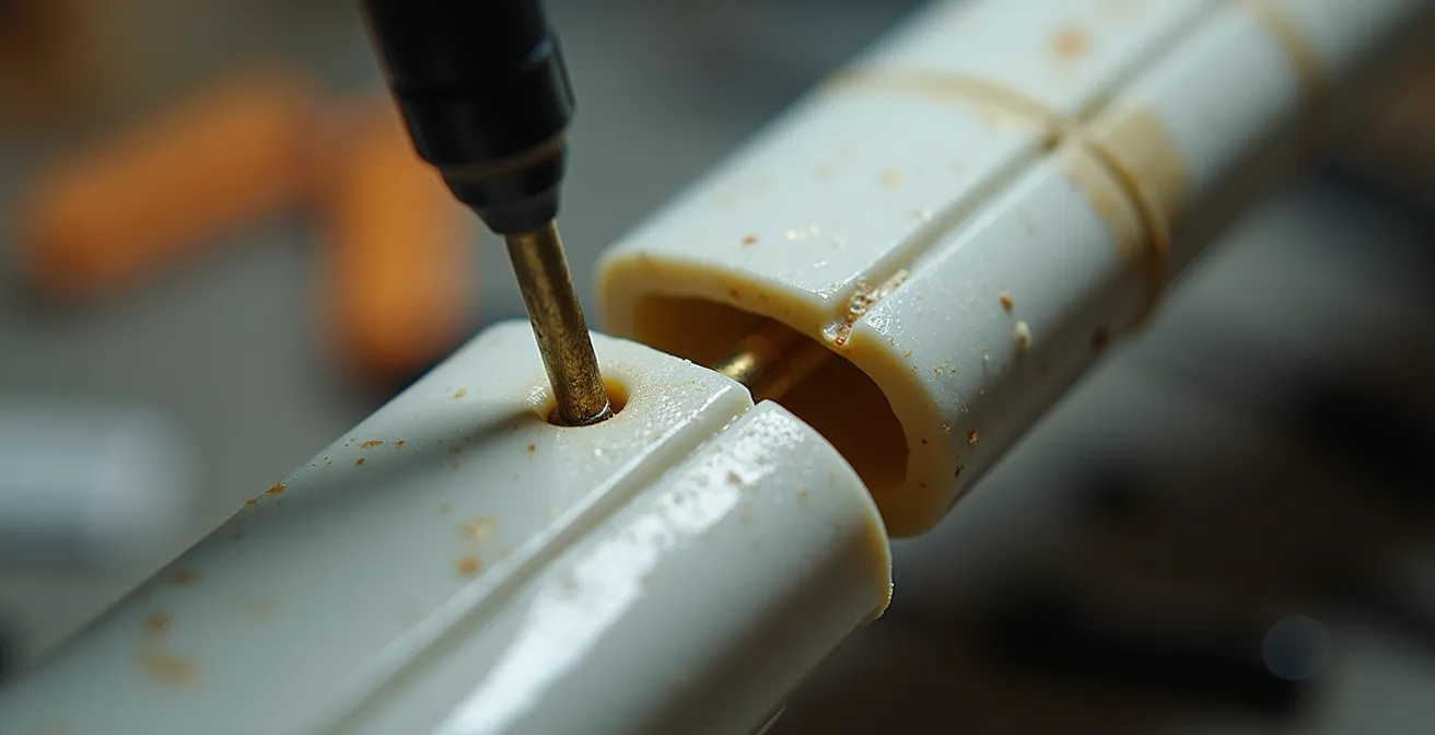
Drilling and Pinning: how to insert a metal core into a plastic strut?
The fundamental principle of reinforcing a plastic landing gear strut is to create a composite structure. By embedding a stronger material within the plastic, you transfer the load from the flexible outer shell to a rigid inner core. While a simple paperclip can provide some benefit, a true structural solution requires selecting a material based on its engineering properties. The goal is to maximize tensile strength and stiffness while minimizing added weight and complexity. Materials like steel wire, brass tubing, and carbon fiber rods each offer a different balance of these characteristics.
The process involves more than just drilling a hole. The diameter of the pilot hole must be carefully chosen to be slightly smaller than the reinforcing rod to ensure a tight fit and prevent splitting the plastic. For non-circular reinforcements like square brass tubing, the hole must be meticulously shaped to match. Square tubing provides a superior bond surface for adhesives compared to round rods. The key is to create an assembly where the reinforcement and the plastic act as a single, unified component. The adhesive isn’t just a filler; it is the medium that transfers stress between the two materials.
A proper reinforcement provides a rigid skeleton that resists bending and torsional forces far more effectively than plastic alone. The plastic strut becomes a fairing, providing the correct shape, while the metal core handles the structural load. This method is often more reliable than simply replacing the part, as it maintains the kit’s original fit and detail while vastly improving its mechanical performance.
This comparative table illustrates the trade-offs between common reinforcement materials, helping you make an informed engineering decision for your specific project’s needs.
| Material | Tensile Strength | Weight Factor | Workability | Best Application |
|---|---|---|---|---|
| Steel Wire (2mm) | Very High | Heavy | Difficult | Large scale models |
| Brass Tubing | High | Moderate | Easy | Medium models with resin |
| Carbon Fiber Rod | Highest | Lightest | Moderate | Competition models |
| Aluminum Rod | Moderate | Light | Easy | Sport models |
Ultimately, a successful reinforcement is a permanent engineering solution that addresses the root cause of plastic failure, ensuring the model’s structural integrity for its entire display life.
Why landing gear spreads over time and how to set the correct angle?
The slow, outward splaying of plastic landing gear is not a sign of a bad glue joint, but a textbook example of a material phenomenon known as plastic creep. Styrene plastic, like many polymers, is a viscoelastic material. This means that when subjected to a constant stress—such as the weight of a heavy model—it will continue to deform slowly over time, even if the load is well below its breaking point. The molecular chains within the plastic gradually slide past one another, resulting in a permanent change in shape. This is why a model can look perfect for months, only to exhibit a noticeable sag a year later.
This process is accelerated by environmental factors. An increase in ambient temperature gives the polymer chains more energy, allowing them to move and deform more easily. Therefore, a model displayed in a warm room or exposed to direct sunlight will experience creep much faster. Detailed analysis confirms this, as research on polycarbonate deformation shows that continuous stress over thousands of hours can drastically reduce a plastic’s stiffness, or its modulus of elasticity. With increasing temperature and creep stress, the creep strain increases and the time to failure decreases, making this a critical consideration for models intended for long-term display.
To counteract this, setting the correct initial angle is crucial, but it must be done within a system that prevents creep. This is where an alignment jig becomes an indispensable engineering tool. A jig holds the fuselage perfectly level and provides precise reference points for the rake and splay angles of each gear leg. By fixing the gear in this zero-stress position while the adhesive cures, you ensure that the geometry is locked in correctly from the start. Without a jig, it is nearly impossible to guarantee that all wheels will touch the ground evenly and that the angles are symmetrical.
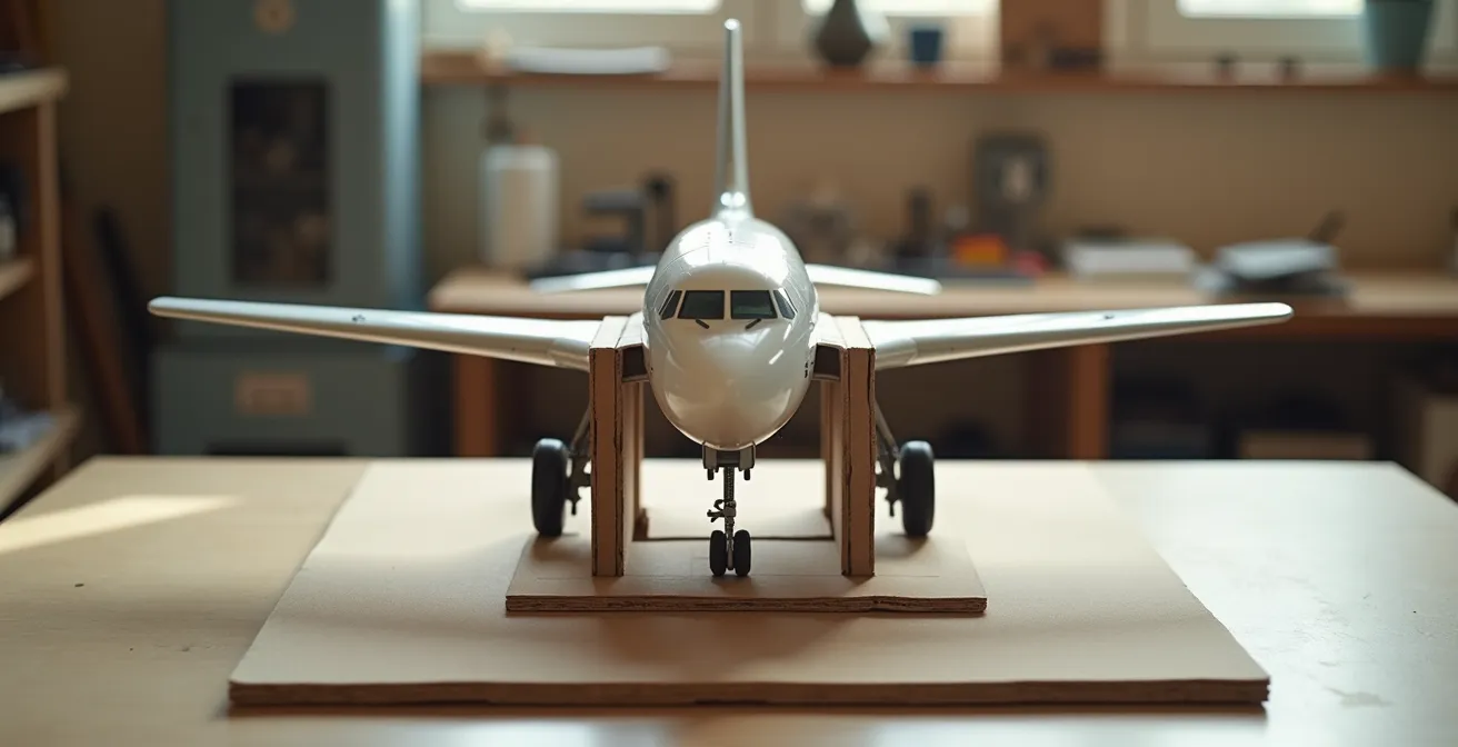
As this setup demonstrates, a jig allows the builder to work against fixed geometric planes, removing guesswork and ensuring a perfectly aligned and stable undercarriage. This tool is not just for alignment; it is a fundamental device for mitigating the long-term effects of plastic creep by ensuring a sound structural foundation.
By recognizing plastic creep as the primary adversary, the focus shifts from simple gluing to building a stable, engineered structure that can resist deformation over decades.
Is it worth replacing the kit gear with aftermarket white metal legs?
Replacing stock plastic landing gear with aftermarket metal parts is a popular solution for heavy conversions, but it is not a universal panacea. The decision involves a cost-benefit analysis that weighs initial expense, time investment, and long-term reliability. White metal, a tin-based alloy, is significantly stronger and stiffer than styrene plastic, offering excellent resistance to the “creep” that causes plastic to sag. For many modelers, the peace of mind and quick installation make it a worthwhile investment.
However, white metal has its own set of structural drawbacks. It is much heavier than plastic, which can shift the model’s center of gravity. More importantly, while it resists creep, it is also relatively soft and can bend under a sharp impact, such as a drop or mishandling. Unlike some plastics, it does not spring back and can be difficult to straighten perfectly once deformed. Furthermore, the quality of white metal castings can vary, sometimes requiring significant cleanup and fitting. In contrast, reinforcing the kit’s plastic gear with a steel or brass core often yields a stronger, more resilient result at a fraction of the cost.
Other alternatives like investment-cast brass or 3D-printed resin offer their own advantages. Brass is extremely strong and dimensionally stable, representing the pinnacle of reliability, but it comes at a premium price. Modern 3D-printed engineering resins can be designed to be both strong and lightweight, offering a custom solution for unique projects, as seen in the development of landing gear for large-scale RC aircraft where strength and durability are paramount.
The following table provides a clear analysis of the trade-offs, allowing you to choose the option that best fits your budget, timeline, and structural requirements.
| Option | Cost Range | Time Investment | Long-term Reliability | Weight Impact |
|---|---|---|---|---|
| Pin Reinforcement | $5-10 | 1-2 hours | Good (5-10 years) | Minimal (+5g) |
| White Metal Gear | $40-80 | 30 minutes | Variable (may bend) | Moderate (+15-25g) |
| Brass Investment Cast | $60-120 | 30 minutes | Excellent (10+ years) | Higher (+20-30g) |
| 3D Printed Resin | $30-60 | 2+ hours print time | Good with proper design | Low (+10g) |
Ultimately, the “best” option is the one that provides the required structural performance within the project’s constraints. Reinforcement offers a low-cost, high-performance path, while high-quality aftermarket parts provide a convenient, reliable alternative.
Why CA glue shears off on landing gear and why epoxy is better?
The frequent failure of cyanoacrylate (CA or “super glue”) joints on landing gear is a direct result of its poor performance under a specific type of force: shear stress. While CA glue has excellent tensile strength (resistance to being pulled apart), it is notoriously brittle and has very low shear strength. Shear stress occurs when forces act parallel to the surface of the joint, attempting to slide the two parts past each other. A landing gear strut, angled to support the model’s weight, transfers a significant portion of that load as shear force at its attachment point to the wing or fuselage.
Under this constant shear load, the brittle CA bond can fracture suddenly and without warning. It is simply the wrong type of adhesive for a critical, load-bearing structural joint. In contrast, two-part epoxy is engineered to excel in these conditions. Epoxy cures through a chemical reaction that forms long, cross-linked polymer chains, creating a bond that is both incredibly strong and slightly flexible. This flexibility allows it to absorb and distribute stress, including shear and torsional loads, far more effectively than the rigid structure of cured CA.
The difference in material properties is quantifiable. In fact, aerospace adhesive testing demonstrates that the shear strength of a typical epoxy (30-45 MPa) can be double that of cyanoacrylate (15-25 MPa). For a structural application like landing gear, this is not a minor difference; it is the deciding factor between a temporary joint and a permanent bond. To maximize this strength, a slow-cure epoxy (24-hour) is always preferable, as it allows more time for the chemical cross-linking to complete, resulting in a tougher, more resilient joint.
Proper application is just as critical as selection. The following steps are essential for creating a successful epoxy bond:
- Choose a 24-hour cure epoxy for maximum strength and flexibility.
- Thoroughly clean and abrade all bonding surfaces to create a mechanical key.
- Mix the two-part epoxy precisely according to the manufacturer’s ratio.
- Apply a thin, even layer; a thick, messy joint is weaker, not stronger.
- Consider toughened or “rubberized” epoxy formulations for parts subject to vibration.
- Allow the assembly to cure fully in a jig at room temperature before applying any stress.
By selecting an adhesive based on its ability to handle shear stress, you are addressing a primary failure point and ensuring the connection is as strong as the parts it joins.
How to use a simple cardboard jig to ensure all wheels touch the ground?
A structural alignment jig is one of the most effective yet underutilized tools in aircraft modeling. Its purpose extends beyond simple alignment; it is an engineering device used to create a geometrically perfect and stress-free assembly. For landing gear, this means ensuring that the aircraft’s weight is distributed exactly as intended, with all wheels making firm, even contact with the ground. A simple jig, constructed from common materials like cardboard or foamcore, can achieve a level of precision that is impossible to attain by eye alone.
The core principle is to establish a set of known, true datums. The jig supports the model’s fuselage and wings perfectly level, creating a fixed reference plane parallel to the ground. From this stable foundation, you can construct vertical supports and use protractors or digital angle gauges to set the precise splay (outward angle) and rake (forward or aft angle) of the landing gear struts. This methodical approach eliminates the frustrating “three-wheeler” problem where one wheel hovers slightly off the surface, which indicates a twist or imbalance in the undercarriage structure.
By building and using a jig, you control the final geometry. The parts are held in their exact final positions while the slow-cure epoxy hardens. This process locks in the perfect alignment, ensuring that once the model is placed on its wheels, the static load is distributed evenly across all contact points. This prevents uneven stress on individual struts, which could accelerate plastic creep and lead to long-term deformation. This technique is standard practice among professional RC builders, who require absolute precision for gear that must not only support weight but also retract into tight fuselage or wing bays.
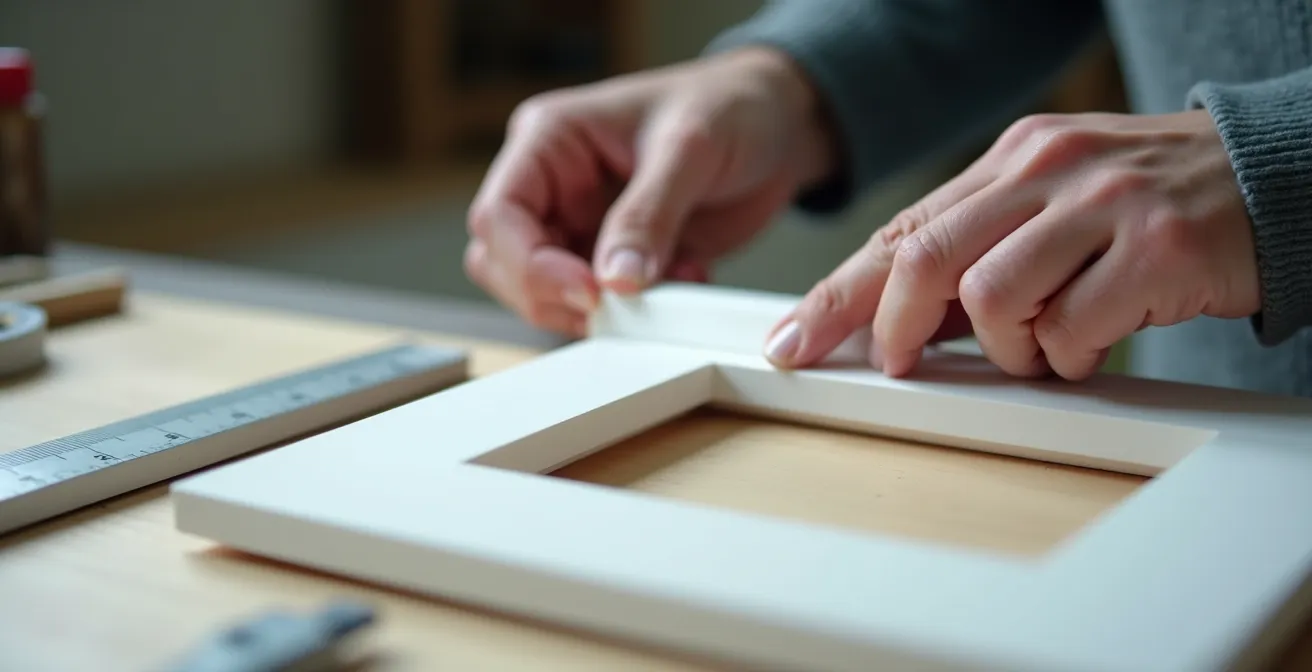
The construction of a jig is an exercise in precision. Using simple materials like foamcore, rulers, and tape, a modeler can create a custom fixture that guarantees a perfect stance. This is not just a building aid; it is a fundamental part of the structural engineering process for a high-quality model.
By investing a small amount of time in building a jig, you are ensuring the final stance and stability of your model will be flawless and permanent.
Why do die-cast metal models outperform plastic in long-term structural integrity?
While the title references “investment portfolios,” the underlying principle is one of material science and long-term value preservation, which is directly applicable to a display model’s structural longevity. A die-cast metal model inherently resists the primary forces that degrade a plastic model over time. The “outperformance” is not financial, but physical. Metal, due to its crystalline atomic structure and high modulus of elasticity, is vastly more resistant to the phenomenon of plastic creep.
As previously discussed, a plastic model under its own weight will slowly deform. A heavy resin conversion accelerates this process dramatically. Metal, by contrast, will not deform under the static loads encountered in a display environment. Its shape is dimensionally stable for centuries. This is why a 20-year-old die-cast model will stand with the same geometric precision as the day it was made, whereas a plastic kit from the same era, especially one with heavy parts, will almost certainly show signs of sagging or warping.
The science behind this is clear. Studies on polymer engineering show how quickly plastic deforms under constant load. For example, specific creep testing on polypropylene demonstrates that viscous strain increases dramatically in a short period, more than doubling in under 24 hours. While styrene has different properties, the principle is the same. This inherent material instability is the primary enemy of a heavy plastic model’s longevity.
Therefore, when considering long-term display, a reinforced plastic model can be seen as an engineered solution to mimic the stability of die-cast metal. By inserting a metal core, you are essentially creating a hybrid structure that leverages a metal skeleton to provide the creep resistance that the plastic shell lacks. The “value retention” is not in resale value, but in the preservation of the builder’s work and the model’s aesthetic and structural integrity over a human lifetime.
Choosing to reinforce plastic or use metal parts is a decision to build a model with the permanence of a die-cast collectible, ensuring it remains a source of pride for decades to come.
Key Takeaways
- The primary threat to heavy models is not sudden breakage but gradual deformation caused by plastic creep, a time-dependent material failure.
- Structural reinforcement with a metal core and the use of high-shear-strength epoxy are engineering requirements, not optional upgrades.
- A precision alignment jig is a non-negotiable tool to ensure a geometrically correct and stress-free assembly for long-term stability.
Why must you treat resin parts differently than plastic to avoid structural failure?
Handling resin components requires a shift in mindset, both for personal safety and for structural engineering. While the dust created from sanding resin is a serious health hazard requiring a respirator, the material’s physical properties also present a unique structural challenge. Polyurethane resin used in conversion kits is significantly denser and more brittle than the styrene plastic of the base kit. This added weight is the primary driver for landing gear reinforcement, but the material’s brittleness and susceptibility to creep also demand careful consideration.
Because resin is so much heavier, the first step is to quantify the problem. Guesswork is not an engineering approach. You must calculate the additional load the landing gear will be forced to bear. This involves weighing the stock plastic parts and comparing them to the new resin components. As analysis of plastic creep shows, the level of stress in a material directly determines how quickly it will deform over time. By adding significant weight, you are dramatically increasing this stress, which in turn accelerates the rate of plastic creep in the landing gear and wing spars.
If the calculated load approaches a significant fraction of the plastic’s yield strength, reinforcement is not just recommended; it is mandatory. Furthermore, because resin is brittle, it cannot be flexed or forced into place like plastic. Attachment points must be perfectly aligned, and joints must be secured with an adhesive that can handle the increased load without failing, which means using epoxy, not CA glue. The entire structure, from the gear attachment points to the wing root, must be assessed for its ability to handle the new, higher stress concentrations.
Action Plan: Calculating Resin Weight Load on Landing Gear
- Weigh all resin components intended for the model using a precision scale.
- Calculate the total additional weight compared to the original stock plastic parts.
- Identify the stress concentration points, primarily where the landing gear attaches to the airframe.
- Apply a safety factor of at least 2x to account for dynamic loads and long-term material fatigue.
- Compare the calculated final load to the known yield strength of styrene plastic.
- If the total load exceeds 50-60% of the plastic’s estimated yield strength, reinforcement is structurally required.
By quantifying the load and respecting the material’s properties, you can engineer a solution that safely accommodates the extra weight for a stable and durable final model.
How do you build custom display stands that support heavy models?
The ultimate solution to preserving a heavy model’s structural integrity is to bypass the problem entirely: take the weight off the landing gear. A custom display stand is not just an aesthetic choice but a long-term engineering strategy for preservation. The ideal stand provides zero-stress support, carrying the model’s full weight via its strongest structural element—typically the fuselage or wing box—and allowing the delicate landing gear to exist purely for visual accuracy, bearing no load whatsoever.
There are several methods for achieving this, each with trade-offs in visibility, complexity, and stability. The most effective and discreet method is the “in-flight” rod support. This involves mounting a strong metal pole (often brass or steel) to a heavy, stable base. This pole inserts into a corresponding tube that has been epoxied deep within the model’s fuselage during construction. When displayed, the model’s weight is transferred directly through the pole to the base, rendering the landing gear completely non-load-bearing. The visible evidence of the stand is minimal, preserving the model’s clean lines.
Other options, like a maintenance cradle, provide excellent support but are more visually intrusive. An integrated diorama base can cleverly hide support structures within scenic elements, distributing the load in a less obvious way. The worst option for a heavy model is a traditional base that still requires the model to rest on its own wheels, as this does nothing to mitigate the forces of creep and shear stress on the undercarriage.
This table compares the most common support methods, evaluating them from a structural engineering perspective to help you select the best long-term preservation strategy.
| Support Type | Weight Capacity | Visibility | Installation Difficulty | Gear Stress |
|---|---|---|---|---|
| Traditional Base Stand | Limited | High | Easy | 100% on gear |
| In-Flight Rod | Excellent | Minimal | Moderate | 0% on gear |
| Maintenance Cradle | Excellent | Moderate | Complex | 0% on gear |
| Integrated Diorama | Very Good | Hidden | Complex | 10-20% on gear |
By implementing a zero-stress display solution, you are making the final and most important engineering decision to guarantee your model’s structural integrity indefinitely. Apply these structural principles to your next build, and you will create a masterpiece engineered to last.