The biggest mistake in model building is following the instruction manual’s sequence, which is designed for assembly clarity, not for a perfect paint finish.
- Treat your model kit like a manufacturing process, breaking it down into logical sub-assemblies that can be painted and finished independently.
- Use “process bottlenecks” like glue curing time to work on other sub-assemblies in parallel, dramatically increasing efficiency.
Recommendation: Before applying any glue, create a custom build plan by dry-fitting all major components to identify and sequence around potential “paint traps.”
Every intermediate modeler knows the feeling: a moment of pure frustration when you realize the fuselage halves are permanently sealed, entombing an unpainted cockpit or leaving intricate wheel wells impossible to reach with an airbrush. The common advice is to “follow the instructions” or simply “be more patient.” But this advice misses the fundamental conflict at the heart of the hobby. Kit instructions are optimized to be understood by the widest possible audience, showing the simplest path to a finished shape. They are not, however, optimized for a high-quality finish.
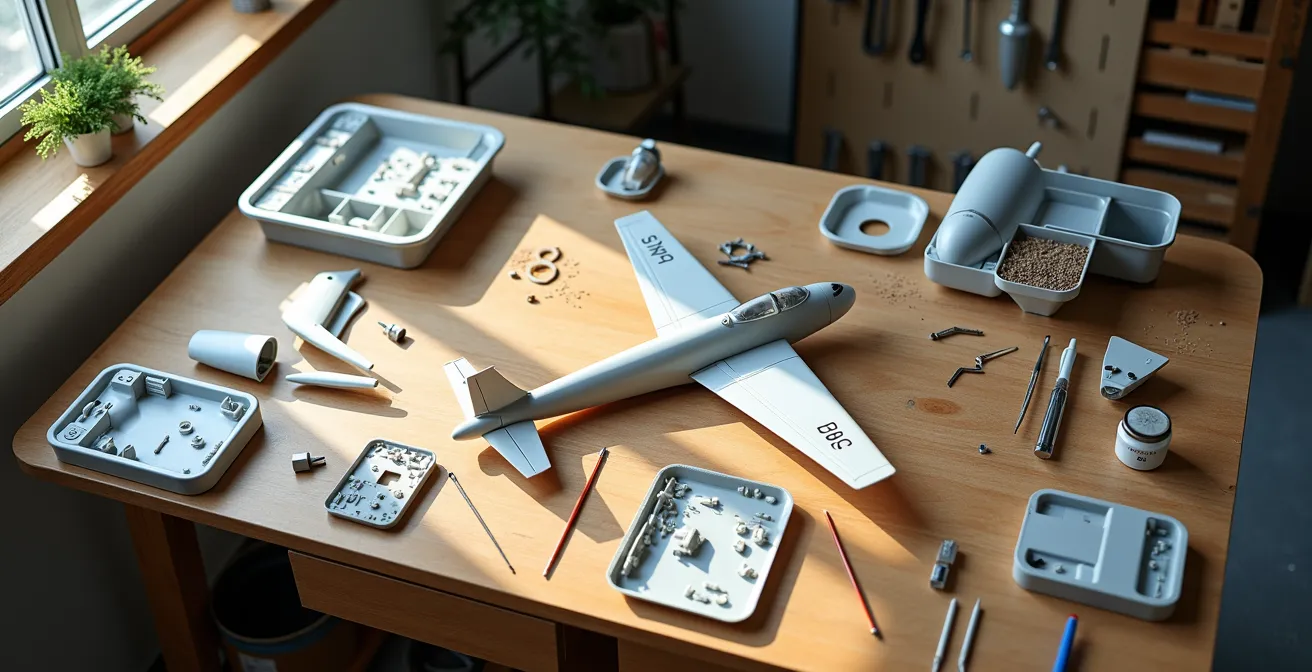
The solution isn’t to work slower; it’s to work smarter by adopting a new mindset. Instead of being a builder who follows a manual, you must become a process engineer who designs a workflow. The key is to deconstruct the kit’s linear sequence and re-organize it into a series of logical sub-assemblies. This approach prioritizes paint and weathering access above all else, ensuring that no part is ever rendered inaccessible by a premature drop of glue. It transforms the build from a sequence of frustrating surprises into a predictable and efficient manufacturing process.
This guide will walk you through this workflow optimization, treating your model kit not as a toy, but as a small-scale industrial project. We will establish quality control gates, identify process bottlenecks, and create a custom assembly sequence that guarantees a superior finish. By mastering these principles, you will eliminate the most common and disastrous assembly errors for good.
Summary: A Process-Oriented Approach to Model Kit Assembly
- Why Dry-Fitting Every Part Saves You Hours of Filling and Sanding Later?
- How to Remove Parts from Sprues Without Gouging the Plastic Surface?
- Thin vs Thick Cement: Which Glue Works Best for Joining Fuselage Halves?
- Why Painting Cockpit Interiors Before Fuselage Closure Is Non-Negotiable?
- How to Work on Landing Gear While the Fuselage Glue Cures?
- Follow or Modify: When Should You Ignore the Manufacturer’s Assembly Order?
- The Assembly Mistake That Makes Masking the Wheel Wells Impossible
- In What Order Should Antennae and Pitot Tubes Be Attached to Avoid Breakage?
Why Dry-Fitting Every Part Saves You Hours of Filling and Sanding Later?
In any manufacturing process, the most critical phase is quality control. For a modeler, this isn’t a final inspection; it’s a foundational step called dry-fitting. This is your primary quality gate. It’s not simply about checking if two parts fit; it’s about simulating the entire assembly sequence without commitment. This proactive step allows you to identify potential issues like warped parts, ejector pin marks in visible areas, and seam line gaps before they become permanent problems sealed with cement. It is, without a doubt, the single most effective technique for reducing time spent on remedial work like filling and sanding.
Think of dry-fitting as creating the blueprint for your unique build plan. As you test-fit wings to the fuselage or canopy to the cockpit sill, you’re not just checking for gaps. You are actively rehearsing the build, identifying which sub-assemblies can be built and painted separately, and noting exactly where you will need to deviate from the manufacturer’s instructions. An expert opinion confirms that the difference between an ordinary model and a masterpiece lies in meticulous preparation like this. It is a time investment of mere minutes that pays back hours in saved frustration.
To formalize this process, adopt a systematic method. As you dry-fit, use a soft pencil to make small marks on mating surfaces that need sanding or trimming. Take notes directly on the instruction sheet, circling problematic steps or drawing arrows to indicate a better sequence. This transforms the generic instruction manual into a personalized workflow document tailored to your specific kit and desired finish quality.
Your Action Plan: The Dry-Fit to Build-Plan Method
- Test fit all major sub-assembly parts before opening any glue.
- Mark directly on parts with a pencil where sanding or trimming is needed for a perfect fit.
- Note problem areas and sequence changes on the instruction manual with arrows and comments.
- Check for any gaps that will require filling with putty or plastic shims.
- Identify steps or misalignments that would create a “paint trap” later in the build.
By treating dry-fitting as a strategic planning session rather than a simple fit check, you shift from reacting to problems to preventing them entirely.
How to Remove Parts from Sprues Without Gouging the Plastic Surface?
The first physical interaction with your kit is removing parts from the sprue, or runner. This “initial material processing” step is often where the first, irreversible damage occurs. Many modelers, in a rush to begin assembly, either twist parts off or cut them flush against the surface. Both methods are high-risk. Twisting can tear chunks from the part, while cutting flush with standard-gauge cutters can exert pressure that creates stress marks or gouges the plastic. This damage requires filling and sanding, adding unnecessary time and effort to the workflow.
A far superior, process-driven approach is the “two-cut method.” This technique isolates the part from the stress of the main sprue frame, allowing for a precise and clean final separation. It treats the sprue gate not as an inconvenience to be ripped away, but as a manufacturing remnant to be methodically removed. This level of care at the very beginning of the process prevents compounding errors and ensures that the part’s geometry remains intact, which is critical for the later dry-fitting and assembly stages.
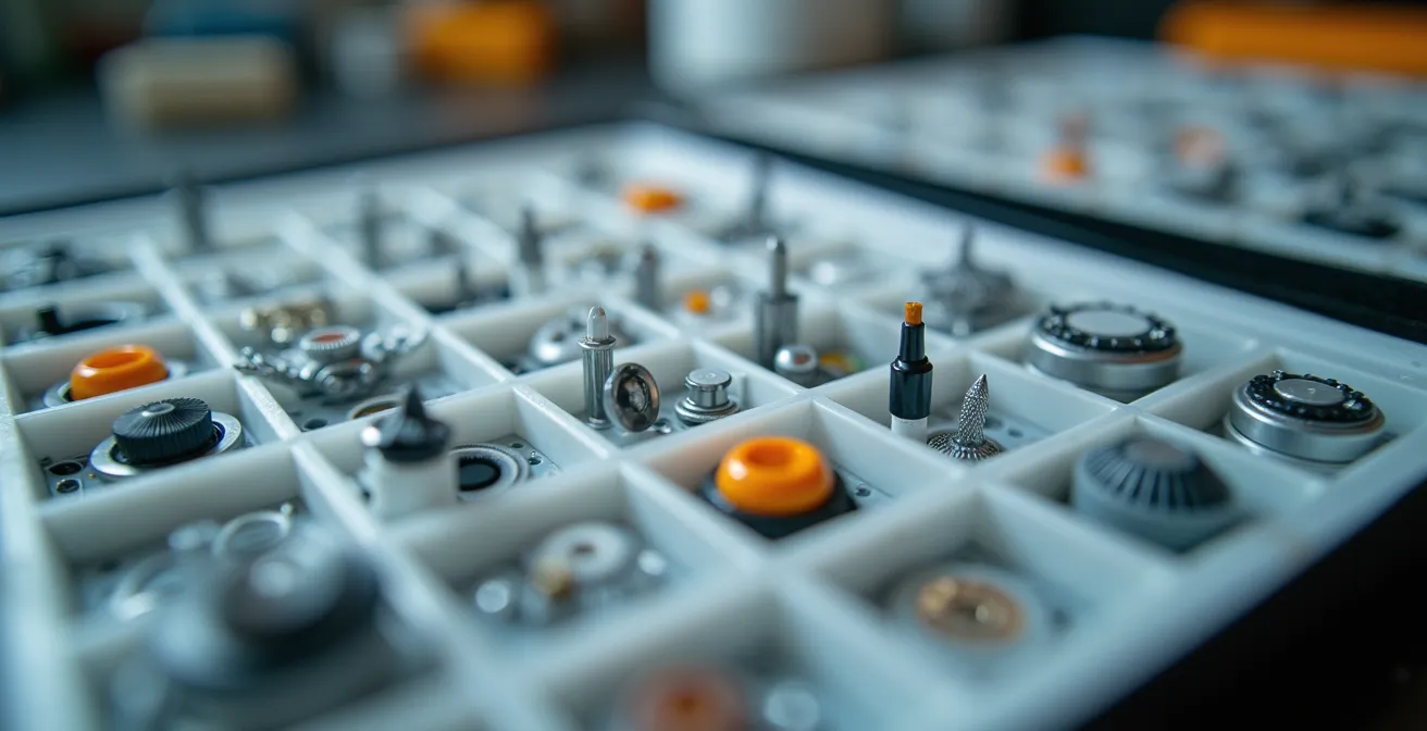
For maximum efficiency, professional modelers often employ a batch processing strategy. Instead of cutting parts as they are needed, they dedicate a session to removing and cleaning all the parts for a major sub-assembly (like the cockpit or landing gear) at once. The cleaned parts are then stored in labeled, compartmented trays. This minimizes tool switching, reduces the risk of losing small components, and streamlines the subsequent assembly and painting phases.
- First Cut: Using standard sprue cutters, make your initial cut 2-3mm away from the part itself, on the sprue runner. This detaches the part from the tension of the main frame.
- Second Cut: Switch to a high-quality, single-blade nipper or a sharp hobby knife. Place the blade flush against the part’s surface and slice off the remaining sprue nub. Always cut away from visible surfaces to minimize the impact of any slip.
- Finishing: If a tiny nub remains, gently sand it smooth with a fine-grit sanding stick. Run your fingertip over the surface to feel for any imperfections your eye might miss.
This disciplined approach to part removal is the first step in treating your model not as a toy, but as a precision engineering project.
Thin vs Thick Cement: Which Glue Works Best for Joining Fuselage Halves?
Once parts are cleanly removed and prepared, the next process is joining them. The choice of adhesive is not trivial; it’s a decision that impacts structural integrity, seam quality, and workflow timing. For major structural joints like fuselage halves, the optimal method involves a two-stage application using both thick and extra-thin polystyrene cements. These are not glues in the traditional sense; they are welding agents that momentarily melt the plastic, fusing the parts into a single, monolithic piece for a powerful bond.
Thick cement, with its slower evaporation rate, is applied to the mating surfaces before they are joined. This provides the primary structural bond. After the halves are pressed together and secured with tape or clamps, extra-thin cement is run along the exterior seam line. This cement works by capillary action, wicking itself into any remaining hairline gaps and creating a perfectly smooth, welded seam that often requires no filling. This two-step technique leverages the best properties of each cement type: the strength of thick cement and the finishing quality of thin cement.
Understanding the properties of different adhesives is crucial for process planning. The table below outlines a selection matrix for the most common types of model cement, allowing you to choose the right tool for each specific task in your assembly workflow.
| Glue Type | Best Use | Working Time | Application Method |
|---|---|---|---|
| Thick Cement | Structural joints, gap-filling | 30-60 seconds | Apply to surfaces before joining |
| Extra-Thin Cement | Pre-fitted parts, seam sealing | 5-10 seconds | Capillary action along joints |
| CA Glue | Photo-etch, dissimilar materials | Instant | Precise drops on contact points |
| PVA/White Glue | Clear parts, canopies | 5-10 minutes | Brush application |
A critical process variable is curing time. While the initial bond forms quickly, achieving full structural strength is a much longer process. According to professional builders, you should plan for an 8-12 hours curing time for thick cement on fuselages. This waiting period is not downtime; it’s a “process bottleneck” that creates a perfect opportunity for parallel work on other sub-assemblies.
By selecting the right cement and understanding its properties, you turn a simple joining step into a controlled and predictable part of the manufacturing process.
Why Painting Cockpit Interiors Before Fuselage Closure Is Non-Negotiable?
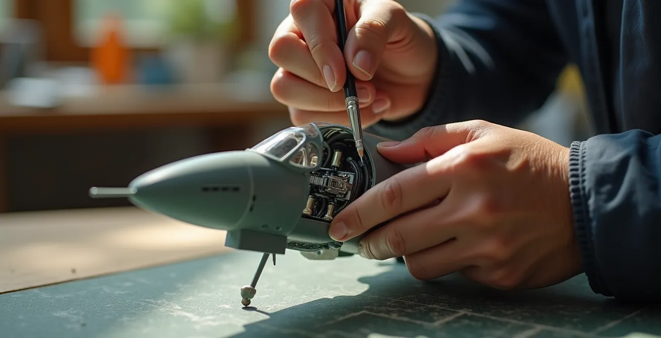
The cockpit is the first major sub-assembly where the “paint-then-assemble” philosophy becomes critical. Once the fuselage halves are joined, the interior becomes a “paint trap”—a sealed box with extremely limited access. Attempting to paint through the small canopy opening is a recipe for overspray, poor coverage, and immense frustration. Therefore, the cockpit must be treated as a self-contained module, to be fully constructed, painted, weathered, and detailed before it is installed into the fuselage.
This sub-assembly workflow involves painting all interior surfaces, applying instrument panel decals while the parts are flat and accessible, adding washes for depth, and dry-brushing to highlight raised details. It’s only after all these finishing steps are complete and sealed with a matte varnish that the cockpit tub is ready for integration. This methodical approach ensures a high level of detail that is simply impossible to achieve post-assembly.
When detailing, it’s easy to get carried away. Adhering to an engineering principle of efficiency, it’s wise to follow the advice of legendary modeler Shep Paine, who famously stated that you should focus your efforts on what will actually be seen. As he wrote in his book, “How To Build Dioramas”:
When it comes to cockpit detailing, only model what can be seen.
– Shep Paine, How To Build Dioramas
This isn’t a call for laziness, but for smart allocation of effort. Focus on the seat, the main instrument panel, and the upper sidewalls—areas visible through the canopy. Deeper, darker areas can be treated more simply, as they will be lost in shadow once the fuselage is closed.
By completing the cockpit as a finished module first, you eliminate one of the most common and demoralizing assembly errors in the hobby.
How to Work on Landing Gear While the Fuselage Glue Cures?
The 8-to-12-hour curing time required for the main fuselage seam is a classic “process bottleneck.” A novice modeler sees this as forced downtime. A process engineer sees it as a scheduled opportunity for parallel work. While the main airframe becomes rigid, your workbench should shift focus to independent sub-assemblies that don’t rely on the fuselage. The landing gear is a prime candidate for this parallel workflow.
Landing gear, with its multiple small parts, complex struts, and delicate hydraulic lines, is a mini-kit in itself. Assembling, cleaning seam lines, painting, and weathering these components while the fuselage cures is an extremely efficient use of time. Other excellent candidates for parallel processing include wing pylons, ordnance (bombs and missiles), external fuel tanks, and tail surfaces. By the time the fuselage is ready for handling, you can have several other major sub-assemblies completed and ready for integration.
To manage this effectively, an organized workspace is essential. Use compartmented trays to keep the parts for each sub-assembly separate and clearly labeled. This prevents parts from being mixed up or lost and allows you to quickly switch between tasks without losing momentum.
This table illustrates how to map out parallel tasks during common curing or drying periods, turning waiting time into productive time.
| Main Assembly Stage | Curing Time | Parallel Work Options |
|---|---|---|
| Fuselage halves joining | 8-12 hours | Landing gear assembly, wing pylons, ordnance preparation |
| Wing assembly | 4-6 hours | Tail surfaces, propeller/jet intakes, canopy masking |
| Major paint coat | 24 hours | Detail parts painting, decal preparation, weathering tests |
This approach transforms a linear, start-and-stop build into a continuous, multi-threaded assembly line, dramatically shortening the total project duration.
Follow or Modify: When Should You Ignore the Manufacturer’s Assembly Order?
The instruction manual is not a sacred text; it is a generic guide. The moment you decide to prioritize a flawless paint finish over simple construction, you must be prepared to question, modify, and re-sequence its steps. The manufacturer’s primary goal is to create instructions that are easy to follow, often leading to sequences that are logical for assembly but disastrous for painting. The decision to deviate should not be random but based on a systematic analysis.
The core reasons for modifying the sequence almost always fall into one of three categories. First, does the official order block access for painting or weathering? (e.g., attaching wings before painting wheel wells). Second, does it require attaching small, fragile parts too early in the process, where they are likely to be broken off during subsequent handling? (e.g., adding antennas before major sanding). Third, can a more stable or cleanly-painted sub-assembly be created by changing the order? (e.g., assembling and painting an engine nacelle completely before attaching it to the wing).
If the answer to any of these questions is “yes,” then you have a clear mandate to modify the workflow. This is where your dry-fitting notes become invaluable. They form the basis of your decision-making, allowing you to confidently re-order steps to serve your goal of a superior finish. This is the essence of shifting from a passive builder to an active process manager.
Checklist: Go/No-Go Framework for Deviating from Instructions
- Access Block: Does the official order block future painting or weathering access to a key area?
- Fragility Risk: Does the sequence require attaching fragile parts (antennas, probes) too early in the process?
- Sub-Assembly Stability: Can a more stable, cleanly-painted sub-assembly be created by changing the part order?
- Instructional vs. Finish Quality: Is the instruction clearly optimized for assembly clarity rather than the quality of the final finish?
- Action: If you answered YES to any of these questions, mark the step for modification and create a new sequence.
By empowering yourself to override the instructions for a logical reason, you take ultimate control over the quality of the final product.
The Assembly Mistake That Makes Masking the Wheel Wells Impossible
Along with the cockpit, the wheel wells are a notorious “paint trap.” These areas are packed with intricate details—hydraulic lines, structural ribs, and wiring—that are a painter’s delight and a masker’s nightmare. The single most common and catastrophic mistake is to follow the instructions blindly and attach the wings to the fuselage before painting this area. Once the wings are on, the wells become dark, cramped caverns where it’s impossible to airbrush cleanly or apply masking effectively.
The correct workflow treats the wing undersides and their corresponding fuselage sections as a single paint job to be completed *before* the wings are permanently attached. The sequence should be: assemble the basic wheel well structures into the wing halves, then paint and weather the entire well area to completion. This includes the base color (often zinc chromate or interior green), detail painting of wires and hydraulics, applying a gloss coat for decals and washes, and a final matte varnish to seal the work.
Only after the wheel wells are 100% finished should they be carefully masked off. A combination of masking tape for the large flat areas and liquid mask for the complex details is ideal. With the wells protected, you can then proceed with attaching the wings to the fuselage, dealing with the resulting seam line, and painting the aircraft’s main camouflage scheme without any risk of overspray into your beautifully detailed wells.
This “paint-mask-assemble” sequence requires more planning than the standard approach but is the only reliable method for achieving a professional-looking result in these complex areas. You can find detailed step-by-step guides on this technique on specialized sites, which often provide a complete wheel well finishing sequence that reinforces this process.
This is a prime example of where ignoring the linear instruction sequence is not just an option, but an absolute necessity for quality work.
Key Takeaways
- The primary goal of assembly sequencing is to ensure paint and weathering access, not just to connect parts.
- Always dry-fit major components to create a custom build plan that identifies and avoids “paint traps.”
- Use unavoidable “process bottlenecks” like glue curing time to efficiently work on independent sub-assemblies in parallel.
In What Order Should Antennae and Pitot Tubes Be Attached to Avoid Breakage?
The final stage of assembly involves attaching the smallest, most fragile parts: antennae, pitot tubes, probes, and other delicate details. The cardinal rule of workflow sequencing is that these parts must be attached absolutely last. Attaching them early, as some instructions suggest, is a near-guarantee that they will be snapped off during the handling, sanding, and masking required for the main painting and decaling stages. This creates frustrating rework and risks damaging the surrounding paint finish.
These components should be painted separately while still attached to a small piece of their sprue for handling. Once the entire model is painted, decaled, weathered, and has received its final clear coat, you can then carefully detach these fragile parts and install them into pre-drilled locating holes using a tiny drop of CA glue or PVA glue. This ensures their delicate structure is not subjected to any of the stresses of the main construction process.
For critical parts like pitot tubes, which are often prominent and easily broken, many experienced modelers proactively replace the flimsy kit plastic with more robust aftermarket alternatives. Metal pitot tubes from manufacturers like Master Model offer a significant upgrade in both detail and durability. Because they are so much stronger, they can sometimes be installed earlier in the build process without fear of breakage, allowing for a more integrated paint finish.
Even with the best planning, accidents happen. Having a contingency plan for repairing a broken antenna is a mark of a prepared modeler. A professional repair technique involves pinning the joint for strength: 1. Drill a tiny hole into both the airframe and the broken part using a pin vise. 2. Insert a small piece of metal wire or a pin into the airframe with a drop of CA glue. 3. Align and attach the antenna to the exposed pin, creating a strong, permanent, and perfectly aligned repair.
By shifting your mindset from a simple builder to a process engineer, you take control of the workflow, prevent errors, and ensure that your time at the bench is more productive and rewarding. To apply this new methodology effectively, your next project should begin not with cutting parts, but with a thorough dry-fitting session to map out your entire assembly and finishing strategy.