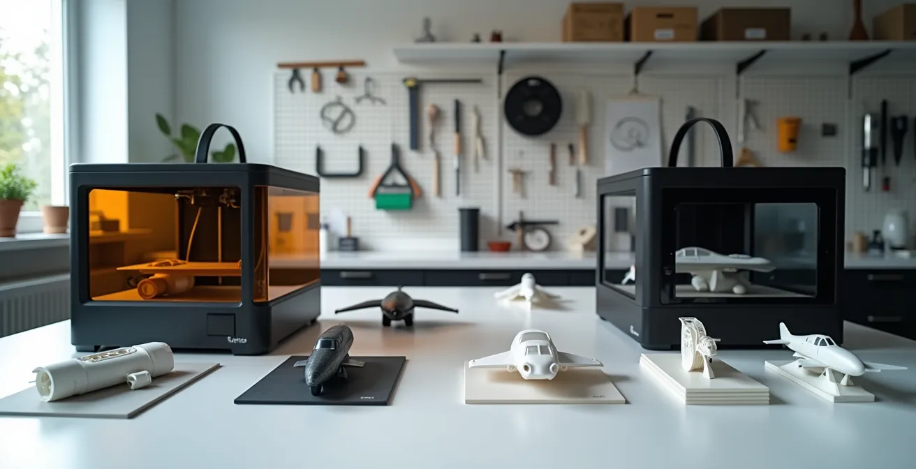
For aircraft modeling, the choice between SLA and FDM is not about cost but about achieving the minimum resolution threshold required for realistic details.
- SLA (Resin) is the only technology capable of reproducing sub-millimeter details like 1/72 scale rivets and cockpit instruments.
- FDM (Filament) fundamentally fails at fine surface features but excels at creating workshop jigs, structural forms, and display stands.
Recommendation: Choose SLA for all high-fidelity detail parts. Integrate FDM only for auxiliary, non-visual components where precision is secondary.
For any serious aircraft modeler, the pursuit of realism is a constant battle. You spend hours researching paint schemes and weathering techniques, only to be let down by the kit’s soft or inaccurate details. The promise of 3D printing—the ability to create any part you can imagine—seems like the ultimate solution. Yet, the community is flooded with conflicting advice. Some champion the low cost of filament printers (FDM), while others insist only resin printers (SLA) will do.
The typical comparison ends with a simple, unhelpful platitude: “SLA is for detail, FDM is for strength.” This oversimplification is a disservice to the modeler considering this investment. It ignores the critical factors that determine success or failure: the physics of resolution at scale, the non-negotiable safety protocols, and the hidden complexities of the post-processing workflow. The decision isn’t just about buying a machine; it’s about committing to an entire ecosystem of design, handling, and finishing.
This guide moves beyond the surface-level debate. We will dissect the *total workflow integration* of each technology specifically for creating high-fidelity aircraft detail parts. We will analyze why one technology fundamentally fails at the task, how to manage the other safely in a home environment, and how to leverage its power to create parts that exceed the quality of even the best aftermarket upgrades. This is not a choice between two printers, but a strategic decision about how you will elevate your modeling for years to come.
To make an informed decision, it’s essential to understand the complete technical landscape. This article breaks down the critical factors, from the fundamental physics of detail rendering to the practicalities of a safe and efficient workshop.
Contents: A Technical Guide to 3D Printing for Aircraft Modelers
- Why filament printers fail to render rivet details on aircraft wings?
- How to set up a safe ventilation system for resin printing in a home office?
- 45-degree rule: how to angle aircraft missiles to minimize support scarring?
- Why your 3D printed wings warp after sitting in the sun (and how to stop it)?
- IPA vs Water Washable: which resin workflow is less messy for a small workshop?
- How to Design Simple Model Parts in CAD Without an Engineering Degree?
- Why You Must Treat Resin Parts Differently Than Plastic to Avoid Lung Damage?
- Which Aftermarket Upgrade Offers the Best Visual ROI for Your Model Kit?
Why filament printers fail to render rivet details on aircraft wings?
A filament (FDM) printer fails to render fine details like rivets due to a fundamental physical limitation: its nozzle diameter. A standard FDM nozzle is 0.4mm wide, meaning the smallest feature it can theoretically produce is a 0.4mm dot of molten plastic. For aircraft models, this resolution is orders of magnitude too coarse. The technology is simply not built for micro-precision.
The problem is one of scale. A real-world 0.5mm rivet on a 1/72 scale model translates to a feature size of just 0.007mm. A mathematical analysis proves it is physically impossible for a 0.4mm nozzle to reproduce this detail. Instead of a crisp rivet, an FDM printer produces a shapeless bump or, more often, nothing at all. The software (slicer) simply ignores details that are smaller than the nozzle’s physical extrusion width. This limitation applies to all fine surface features, including panel lines, instrument bezels, and gun sights, making FDM unsuitable for any part where surface fidelity is the primary goal.
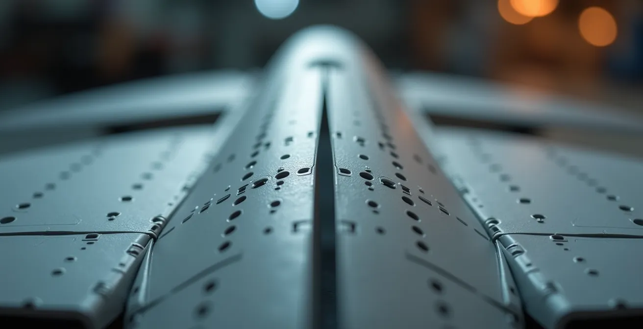
In contrast, Stereolithography (SLA) printers use a laser or UV light source with a spot size as small as 0.05mm to cure liquid resin. This allows them to achieve a resolution threshold far below that of FDM, easily capturing the sub-millimeter details essential for realistic aircraft models. The difference is not incremental; it is a categorical superiority for fine-detail applications.
How to set up a safe ventilation system for resin printing in a home office?
A safe ventilation system for resin printing requires active extraction of volatile organic compounds (VOCs) to the outside. Standard air purifiers are insufficient. The most effective setup involves placing the printer inside an enclosure, such as a grow tent, connected via ducting to an inline fan that vents contaminated air directly out a window.
The fumes from liquid resin are not just an unpleasant odor; they are a mixture of VOCs that pose a health risk. Relying on an open window or a simple desktop air filter is a common but dangerous mistake. Most consumer-grade purifiers use HEPA filters, which capture particulates but do nothing to stop gaseous VOCs. Even those with a thin carbon layer are quickly overwhelmed, as filtration research demonstrates that activated carbon beds 1-2 inches thick only capture 40-60% of VOCs per pass. This is not adequate for continuous exposure in a living space.
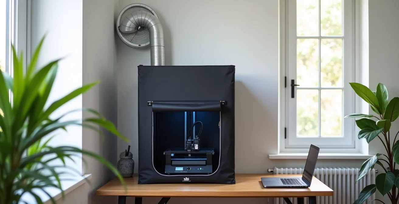
A proven and cost-effective solution for a home office involves three components: a sealed enclosure, ducting, and a powerful inline fan. An affordable grow tent ($50-$100) provides an excellent enclosure. An inline duct fan (4-inch diameter is standard) is mounted in the ducting line to actively pull air from the tent and push it outside. This creates negative pressure, ensuring that no fumes escape into the room when the enclosure is sealed. For maximum safety, an activated carbon filter can be placed in the line to capture a portion of the VOCs before they are vented, protecting both the operator and the environment.
45-degree rule: how to angle aircraft missiles to minimize support scarring?
The “45-degree rule” is a generalized starting point for orienting parts, but for cylindrical objects like aircraft missiles, it is an inferior strategy. The optimal orientation is a custom angle that places all support contacts on a single, non-visible surface, such as the pylon mounting point, to completely eliminate visible scarring after removal.
When you orient a missile at 45 degrees, the slicer software will place support touchpoints along the entire underside of the cylinder. While this supports the part, it creates a line of tiny pockmarks that are tedious to sand and often remain visible after priming. A better approach is to orient the missile vertically, which confines supports to the tail fins—an area that is flat and easier to sand. However, the best method is a strategic custom orientation.
By analyzing the final placement of the part on the model, you can identify a surface that will be hidden from view. For a missile, this is almost always the flat surface where it attaches to the wing pylon. By angling the part so this mounting surface faces the build plate, you can instruct the slicer to place all supports exclusively on this sacrificial area. After printing and curing, the entire support structure can be snapped off, leaving a perfectly clean, scar-free visible surface. The mounting face may be rough, but this is irrelevant as it will be covered with glue and hidden during final assembly.
Checklist for Optimizing Part Orientation
- Identify Sacrificial Surfaces: Determine which faces of the part will be hidden or glued during assembly. This is your target for support placement.
- Custom Angle Orientation: Tilt the part so the primary sacrificial surface faces the build plate. Avoid default 45-degree or vertical orientations.
- Minimize Contact Points: Use “tree” or “organic” supports with the smallest possible contact point diameter (e.g., 0.15mm) to reduce surface damage.
- Hollow and Drain: For larger cylindrical parts, hollow the model (e.g., 1.5mm wall) and add a small drainage hole on the sacrificial surface to save resin and reduce peel forces.
- Pre-Prime Sanding: After support removal, always wet-sand any remaining marks on visible surfaces *before* applying primer to ensure a flawless finish.
Why your 3D printed wings warp after sitting in the sun (and how to stop it)?
3D printed parts, especially from FDM printers using PLA filament, warp in the sun because their material structure changes at a relatively low temperature. This point, the glass transition temperature (Tg), is where the plastic begins to soften and deform under internal stress. For standard PLA, this process can begin at just 60°C (140°F).
On a hot day, a model placed in direct sunlight or inside a car can easily reach this temperature. The warping is caused by internal stresses locked into the part during the printing process. As each layer is printed and cools, it contracts slightly, creating tension. When the part’s temperature rises to its Tg, the plastic softens enough for this tension to release, causing the part to bend, twist, or sag. This is especially noticeable on long, thin parts like aircraft wings.
For resin (SLA) parts, the problem is different but related. Uncured or under-cured resin will continue to react when exposed to UV light from the sun. This uncontrolled curing creates its own internal stresses, leading to brittleness and warping. The solution for both technologies lies in proper material selection and post-processing. For FDM, using filaments with a higher Tg, like PETG (80°C) or ABS (105°C), is a must for any part that might see sunlight. For SLA, a thorough post-cure cycle is non-negotiable. Curing the part in a dedicated station with controlled UV light and temperature (e.g., 2-4 hours at 60°C) ensures the resin achieves maximum polymerization and becomes dimensionally stable. Furthermore, applying a quality modeling primer, especially a dark one like black or gray, acts as a perfect UV shield, making the finished part inert to further sunlight exposure.
IPA vs Water Washable: which resin workflow is less messy for a small workshop?
Counterintuitively, an Isopropyl Alcohol (IPA)-based workflow is often less messy and more sustainable for a small workshop than using water-washable resins. While water-washable resin seems simpler initially, it creates a hazardous waste problem that is more difficult to manage than recycling IPA.
Water-washable resin’s main appeal is avoiding the need to purchase and handle a flammable solvent. You can simply rinse fresh prints under a tap. However, this convenience is misleading. The rinse water becomes contaminated with liquid resin and is considered hazardous waste. It is illegal and environmentally irresponsible to pour this contaminated water down the drain. To dispose of it properly, you must collect the water, leave it in the sun for days to cure the suspended resin particles, then filter out the solid plastic before the water can be evaporated. This is a slow, messy process that generates significant liquid waste.
An IPA workflow, while requiring the handling of a solvent, is a closed-loop system. You use two containers of IPA: a “dirty” bath for the initial wash and a “clean” bath for the final rinse. Over time, the dirty bath becomes saturated with dissolved resin. Instead of disposing of it, you can place the sealed, clear container in the sun or a UV curing station. The UV light will polymerize the dissolved resin, causing it to fall out of suspension as solid particles. You can then filter the IPA through a coffee filter, and it is completely reusable for the next dirty wash. This generates almost zero liquid waste. The only waste is the small, solid puck of cured resin, which can be disposed of as solid waste.
The following table, based on data from recent industry comparisons, breaks down the hidden trade-offs.
| Factor | IPA-Based Resin | Water-Washable Resin |
|---|---|---|
| Initial Convenience | Requires IPA purchase | Just needs water |
| Waste Disposal | IPA recyclable via UV curing | Hazardous water waste |
| Material Properties | Durable, stable | Brittle, hygroscopic |
| Long-term Cost | Lower (IPA reusable) | Higher (water disposal) |
| Model Longevity | Excellent | Risk of cracking |
How to Design Simple Model Parts in CAD Without an Engineering Degree?
Designing simple replacement or custom parts requires no engineering background, thanks to free, intuitive tools like Tinkercad or Microsoft 3D Builder. The key is to start by modifying existing shapes or “digital kitbashing,” not by trying to design complex objects from a blank slate.
The thought of Computer-Aided Design (CAD) is intimidating for many modelers, who envision complex software with a steep learning curve. While professional tools like Fusion 360 are powerful, they are overkill for most modeling tasks. The process of replacing a simple, flat part like a lost landing gear door can take less than five minutes:
- Measure: Use digital calipers to measure the length and width of the missing part (or the space it fits into).
- Open Tinkercad: This free, web-based software requires no installation.
- Create Shape: Drag a basic rectangle onto the workplane and enter the measurements you took.
- Add Thickness: Use the height tool to set the part’s thickness, typically 0.5mm to 1mm for a gear door.
- Export: Click “Export” to save the file as an STL, ready for your slicer.
A more powerful technique for beginners is digital kitbashing. This involves downloading free, pre-made STL files (e.g., from sites like Thingiverse or Yeggi) and using a simple program like Microsoft 3D Builder to modify them.
Case Study: Digital Kitbashing a Custom Pilot Seat
A modeler building a 1/48 scale P-47 Thunderbolt found the kit’s pilot seat to be generic and lacking detail. Instead of designing one from scratch, they downloaded a free, highly detailed generic pilot seat STL. Using Microsoft 3D Builder, they performed three simple operations: first, they scaled the entire object to the correct 1/48 dimensions. Second, they used the “Split” tool to cut away the armrests, which interfered with the kit’s cockpit tub. Finally, they created a simple block shape to serve as a new headrest and used the “Merge” command to combine it with the seat. The result was a unique, perfectly fitting, and highly detailed part created with zero prior CAD knowledge.
Why You Must Treat Resin Parts Differently Than Plastic to Avoid Lung Damage?
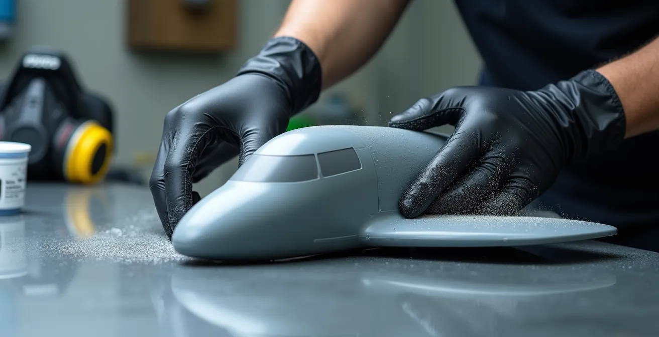
You must treat cured resin parts differently from traditional polystyrene plastic because the dust generated from sanding is a potent sensitizer that can cause permanent lung damage and allergic reactions. Unlike plastic dust, which is a simple irritant, resin dust can trigger a lifelong, irreversible immune response with repeated exposure.
When you sand a typical plastic model kit part, you create fine particles of polystyrene. While not healthy to inhale, these are largely inert irritants. The dust from a fully cured resin part is fundamentally different. It contains microscopic particles of polymerized acrylate or epoxy. As safety research confirms, this cured resin dust is a permanent sensitizer. This means that with each exposure, your body’s immune system can become more reactive. After a certain threshold of exposure—which varies from person to person—your body can develop a severe allergic contact dermatitis or respiratory allergic reaction. Once this sensitization occurs, it is permanent. You may react strongly to even minute amounts of resin dust in the future.
The only safe way to work with cured resin is to prevent its dust from becoming airborne or contacting your skin. This requires a strict, non-negotiable safety protocol:
- Always wet sand. Using water while sanding traps the dust particles in a slurry, preventing them from becoming airborne.
- Wear a respirator. Even when wet sanding, a P100 or N95-rated respirator is mandatory to capture any particles that may still be aerosolized.
- Wear nitrile gloves. Prevent skin contact with the dust slurry, as sensitization can also occur through the skin.
- Work in a well-ventilated area. Ensure any residual particles are quickly removed from your breathing zone.
Key Takeaways
- SLA technology is mandatory for any fine-scale surface details like rivets or panel lines; FDM is physically incapable of this work.
- A safe resin printing workflow requires a dedicated, ducted ventilation system that vents VOCs outside; desktop air purifiers are insufficient.
- Rigorous post-processing, including a controlled UV cure and a UV-blocking primer, is non-negotiable for the stability and longevity of resin parts.
Which Aftermarket Upgrade Offers the Best Visual ROI for Your Model Kit?
While expensive photo-etch and cast resin sets offer high detail, the single upgrade with the best visual Return on Investment (ROI) is often a custom, 3D printed part that solves a specific, glaring inaccuracy in the base kit. The power of 3D printing is not in replacing common items, but in creating what is commercially unavailable.
Modelers often spend significant money on aftermarket sets—a $30 resin cockpit or a $20 photo-etch fret—to improve a model. While these enhance a kit, their impact is often limited to one small area. A 3D printer fundamentally changes this equation. For the cost of a few milliliters of resin (less than $1), you can produce a part that transforms the entire look of a model because it corrects a major flaw that no aftermarket company has addressed. This could be a correctly shaped engine intake, a unique weapons loadout for a specific historical mission, or a detailed undercarriage bay for a kit that provides only a void.
The true value is unlocked when moving beyond simple replacement. Consider creating a custom display base with a realistic tarmac texture or a complete assembly jig that guarantees perfect wing dihedral and alignment. These functional prints cost very little but dramatically improve the final presentation and build quality, offering a massive visual ROI. As one expert notes, the strategy is about hyper-specificity.
The true power of 3D printing isn’t replacing common resin seats, but creating hyper-specific unavailable parts: unique weapons loadouts for specific historical missions, corrected engine intakes for inaccurate kits
– Eric Haddad, Model Aviation – 3D Printing RC Aircraft
By focusing on these high-impact, unavailable parts, the modeler leverages the printer’s core strength. Instead of spending $15 on a common resin ejection seat you could print yourself, you use the printer to create the one part that makes your model uniquely accurate and visually striking.
Ultimately, integrating an SLA printer into your workflow is a strategic investment in creative freedom. By evaluating your specific modeling goals and understanding the complete workflow, you can begin producing parts that were once impossible to obtain, elevating your work to a new level of detail and accuracy.
Frequently Asked Questions About Choosing a 3D Printing Resin
What if minimizing initial chemical odor is my priority?
Choose water-washable resin but you must invest in a proper, ducted ventilation system regardless of the lower odor. You must also accept that the finished parts will have more brittle material properties and a higher risk of cracking over time compared to standard resins.
What if maximizing part durability is critical?
Standard, IPA-based resins are essential for durable and dimensionally stable parts. The superior mechanical properties and long-term stability justify the additional safety protocols required for handling Isopropyl Alcohol.
What about simplifying waste disposal?
Counterintuitively, an IPA-based workflow is simpler for waste disposal. You can cure the dissolved resin out of the IPA with UV light, filter it, and reuse the alcohol indefinitely. Water-washable resin creates contaminated water that is hazardous and requires a more complex, multi-step process to dispose of safely.