The primary cause of failure when installing a resin engine is treating it as a simple assembly job, not the micro-engineering procedure it is.
- Success requires precise material removal to manage heat and stress, not just brute-force sanding.
- Engine alignment must be established using a multi-axis datum, and the model’s center of mass must be recalculated and counterbalanced.
Recommendation: Shift your mindset from ‘builder’ to ‘miniature airframe mechanic’. Think in terms of structural integrity, mass balance, and tolerances.
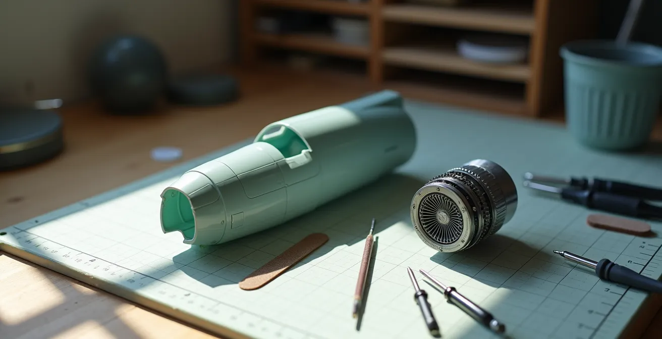
There is a unique moment of both excitement and dread familiar to advanced aircraft modelers. You unbox a stunningly detailed resin engine, a heavy, intricate jewel of casting that promises to elevate your project to a museum-quality piece. Then you look at the thin, fragile plastic cowling of the base kit it’s meant to fit into. The two seem fundamentally incompatible. The common advice is to simply “sand the cowling until it fits,” a platitude that has led to countless cracked cowlings, melted plastic, and misaligned propellers that ruin a model’s silhouette. This approach treats a delicate operation like a brute-force task.
Before any modification, it is critical to prepare the resin itself. All resin parts must be thoroughly washed with warm, soapy water and an old toothbrush to remove mold release agents. These oily residues are invisible but will repel paint and primer, leading to catastrophic paint lift later. This is a non-negotiable first step. The true challenge, however, lies in the integration. It’s not about removing material; it’s about understanding material stress, heat management, and the physics of balance. This isn’t just assembly; it’s surgery. The goal isn’t to make it fit; it’s to re-engineer the forward fuselage to accept a new, heavier powerplant while maintaining perfect structural integrity and alignment.
This guide abandons the “sand and pray” method. Instead, we will dissect the process with the precision of an airframe and powerplant mechanic. We will explore the specific techniques for thinning plastic without compromising its structure, establishing a perfect centerline for the propeller shaft, calculating the shift in the center of gravity, and applying weathering that accentuates, rather than hides, the engine’s exquisite detail. This is the blueprint for a flawless powerplant transplant.
For those who appreciate a hands-on look at the complexities of a full-resin kit build, the following video provides a practical review of constructing the Saab 210 ‘Lill-Draken’. It serves as an excellent case study in handling and assembling resin components, complementing the specific engine integration techniques detailed below.
This article is structured as a series of surgical procedures. Each section addresses a critical phase of the engine integration process, providing the technical data and methodologies required to ensure a successful outcome. Follow these steps to transform a high-risk operation into a controlled and repeatable display of modeling skill.
Summary: A Masterclass in Resin Engine Integration
- Dremel vs Scraper: how to thin the cowling from the inside safely?
- How to center a resin engine so the propeller doesn’t sit off-axis?
- Lead wire or Copper: which material creates the most realistic spark plug leads?
- How a heavy resin engine affects the center of gravity on tricycle gear planes?
- How to apply a wash to deep cylinder fins without creating a black blob?
- Which Aftermarket Upgrade Offers the Best Visual ROI for Your Model Kit?
- How to Paint Realistic Wood Grain on Plastic Propellers?
- How to Create Wet Fluid Leaks That Look Fresh on a Matte Model?
Dremel vs Scraper: how to thin the cowling from the inside safely?
Thinning a plastic cowling is a battle against heat and stress. The primary enemy is the low melting point of polystyrene. A rotary tool like a Dremel, used improperly, will generate friction heat that melts, gums, and distorts the plastic long before it effectively removes it. The surgical approach requires strict heat management. Scrapers, such as a curved X-Acto blade used with the dull side forward, offer maximum control and no heat generation, making them ideal for initial bulk removal and for builders who prioritize safety over speed. However, for a perfectly uniform inner surface, a rotary tool is faster if disciplined.
The key is low speed and the correct bit. For this operation, official guidelines recommend staying at 15,000 RPM or less for plastic. Use a grinding or sanding bit, not a cutting wheel, to abrade the material away. Work in short, 3-5 second bursts on different areas, allowing the plastic to cool. Advanced modelers use a “wet grinding” technique, misting the interior of the cowling with water to actively dissipate heat. Throughout the process, constantly check the wall thickness with digital calipers, aiming for a minimum of 0.5mm to maintain structural integrity.
Case Study: The Anigrand Mirage 4000 Integration
In a documented build of the Anigrand Mirage 4000, a modeler faced this exact challenge. Instead of relying solely on a Dremel, a combination of scraping and sanding was used. Crucially, to prevent the thinned cowling from cracking under the stress of handling, temporary internal bracing made from sprue was installed before thinning began. This maintained the part’s geometry and demonstrates a core principle: you must preserve structural integrity at all costs during the procedure.
Action Plan: Controlled Cowling Thinning
- Start at 5,000-10,000 RPM for plastic materials to prevent heat buildup and melting.
- Use grinding bits rather than cutting discs for controlled material removal.
- Apply the ‘wet grinding’ technique with water mist to dissipate heat during operation.
- Work in short 3-5 second bursts, allowing cooling time between passes.
- Test thickness frequently with calipers, stopping at 0.5mm minimum wall thickness.
How to center a resin engine so the propeller doesn’t sit off-axis?
Visual alignment, or “eyeballing,” is the most common source of error in engine installation. A propeller shaft that is even a fraction of a degree off-axis is immediately noticeable and undermines the entire build. Precision requires establishing an alignment datum, a fixed reference point against which all measurements are made. For this, a long, perfectly straight brass rod is your most critical tool. The process is systematic and must verify alignment on multiple axes before any permanent adhesive is applied.
First, temporarily fix the engine inside the cowling with small balls of blue tack or a similar non-permanent putty. Insert the brass rod through the propeller shaft hole in the resin engine, letting it extend several inches forward. Now, view the assembly from directly above. The brass rod must be perfectly parallel to the fuselage centerline seam. Next, view it from the side. The rod must have the correct vertical thrust angle as specified in the kit’s instructions (it is rarely perfectly level). Adjust the engine’s position with the putty until both horizontal and vertical alignment are perfect. Only then should you use a sharp pencil to mark the engine’s final position relative to the cowling’s interior. For permanent bonding, a two-part epoxy is superior to cyanoacrylate (CA glue) for this task, as it offers a longer working time for final adjustments and has superior gap-filling properties and strength to support the engine’s weight.
The image above demonstrates this principle perfectly. A jig, even one scratch-built from sprue, can hold the engine while a brass rod confirms the thrust line is true. This mechanical verification removes all guesswork from the process, guaranteeing a perfectly centered propeller every time. This is not just about aesthetics; it’s about geometric accuracy.
Lead wire or Copper: which material creates the most realistic spark plug leads?
The choice between lead and copper wire for spark plug ignition harnesses is a choice between convenience and fidelity. Copper wire, often stripped from old electronics, is readily available. However, its inherent springiness makes it difficult to work with. It resists forming the tight, complex bends required to route wires around cylinder heads and often requires super glue at every contact point to hold its shape. Its primary advantage lies in smaller scales like 1/48 or 1/72, where its rigidity can be a benefit and its lack of “drape” is less noticeable.
For larger scales (1/32 and up), lead wire is surgically superior. Its extreme flexibility and lack of memory mean it can be bent into any shape with just your fingertips and it will hold that shape perfectly. This allows for the replication of a crucial detail: natural drape. Real wires and hoses have weight and sag between attachment points. Lead wire replicates this “gravity effect” effortlessly, adding a level of realism that springy copper cannot match. While it does require a primer for paint to adhere properly and necessitates washing hands after handling, the visual payoff is immense.
This is further supported by a case study from Vector Resin, a manufacturer of elite-level engines. In their documentation, they exclusively recommend lead wire to complement their products. They demonstrate that its superior flexibility is the only way for modelers to accurately replicate the precise routing and natural sag of period-correct ignition harnesses, especially on complex WWI and WWII radial engines where wires weave through a maze of pushrods and cooling fins.
The following comparison table breaks down the operational differences between the two materials, making the choice a matter of tactical consideration based on scale and desired outcome.
| Property | Lead Wire | Copper Wire |
|---|---|---|
| Flexibility | Extremely flexible, holds shape perfectly | Moderately flexible, may spring back |
| Natural Drape | Excellent – creates realistic sag | Good – requires more manipulation |
| Scale Appearance | Superior for 1/32 and larger | Better for 1/48 and smaller |
| Workability | Easy to bend, no tools needed | Requires needle-nose pliers |
| Paint Adhesion | Requires primer | Accepts paint directly |
| Safety | Handle with care, wash hands | No special precautions |
How a heavy resin engine affects the center of gravity on tricycle gear planes?
Newton’s laws do not cease to operate at 1/48 scale. Installing a heavy resin engine in the nose of a model with tricycle landing gear dramatically shifts its Center of Mass (CoM) forward. While this solves the common problem of “tail-sitting,” it often creates the opposite issue: an exaggerated, nose-heavy stance where the nose gear is overly compressed. The goal is not simply to prevent tail-sitting, but to achieve a realistic weight distribution where the model rests naturally on its main gear, with the nose gear just lightly touching the ground. This requires a precise counter-balancing procedure.
The balancing act must be performed after the fuselage is assembled with the resin engine installed, but before the wings are attached. The fulcrum for this test is the exact attachment point of the main landing gear. Balance the fuselage on a pencil or a similar narrow object at this point. If the nose tips down sharply, you must add counter-weight aft of the fulcrum. The ideal location is as far back as possible, such as behind the cockpit bulkhead or in the rear fuselage, to maximize its leverage. Use dense materials like lead fishing weights or tungsten putty, secured permanently with two-part epoxy. Add weight incrementally, re-testing the balance until the fuselage sits nearly level, with only a slight tendency to dip forward. This ensures the final model has a correct, stable stance.
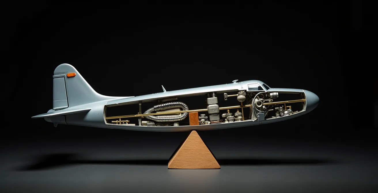
The cutaway view above illustrates this principle. The heavy resin engine in the nose acts as a significant weight. The strategically placed counter-weights behind the cockpit are not just thrown in; they are a calculated mass used to shift the Center of Mass rearward, creating a state of equilibrium around the main gear fulcrum. This is a critical step in achieving engineering realism.
This procedure, as outlined in a guide by Old Model Kits’ blog on resin building, is fundamental. Mastering the model’s balance is as important as any external detailing.
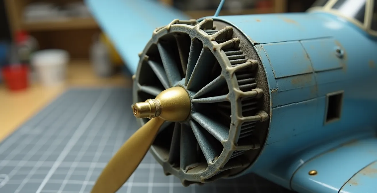
How to apply a wash to deep cylinder fins without creating a black blob?
The deep, finely cast cooling fins on a resin engine are a double-edged sword. They offer incredible detail but are also a perfect trap for washes, which can pool and dry into a black, detail-obscuring mass. Preventing this “black blob” effect requires moving away from the simple “slop it on, wipe it off” technique and adopting a more controlled, two-stage process that leverages capillary action rather than brute force. The goal is to let the wash flow itself into the recesses, not to brush it in.
First, a barrier is essential. After painting the engine’s base metallic colors, apply a solid coat of gloss varnish and let it cure for at least 24 hours. This smooth, non-porous surface is crucial for controlling the wash. The second step is to pre-wet the engine surface with pure mineral spirits or the appropriate thinner for your wash. Immediately apply the wash, which should be highly thinned. Professional modelers recommend starting with an initial wash at a 1:10 ratio of paint to thinner. When this diluted wash touches the pre-wetted surface, capillary action will pull the pigment directly into the panel lines and fin gaps with minimal spreading on the raised surfaces. After about 10 minutes, any excess can be blended or removed with a clean brush just barely dampened with thinner.
This initial, light wash creates a general sense of grime. For deeper shadows, a second, targeted application is needed. This is the “pin wash,” using a darker color mixed to a slightly thicker ratio (e.g., 1:5). Using a fine-tipped brush, apply this wash only into the deepest grooves and junctions, such as the base of each cylinder. This two-stage approach builds up depth and shadow logically, preserving the delicate detail of the fins and creating a look of mechanical complexity rather than a dirty blob.
Which Aftermarket Upgrade Offers the Best Visual ROI for Your Model Kit?
In the world of aftermarket upgrades, modelers face a choice: where to invest time and money for the biggest visual impact. The options range from resin engines and cockpits to photo-etch details and metal landing gear. While every upgrade adds value, their Return on Investment (ROI) varies dramatically based on visibility, complexity, and the model’s final display concept. A cost-benefit analysis reveals a clear hierarchy of impact.
A detailed resin cockpit is often considered a high-impact upgrade because it’s situated in the model’s focal point and is almost always visible through the canopy. Similarly, resin wheels with flattened bottoms add a subtle but significant touch of realism for a relatively low cost and effort. However, the undisputed king of visual ROI, under the right conditions, is the full resin engine. Its complexity and mechanical beauty can become the centerpiece of the entire model, transforming it from a static replica into a piece of miniature engineering. The caveat is that its impact is directly proportional to its visibility. A stunning engine hidden behind closed cowlings has zero visual ROI.
This is where planning becomes paramount. As noted authority Pat Hawkey states in his book, “Building and Detailing Model Aircraft,” a detailed engine offers the highest ROI when the model’s display concept is planned around it from the start. This means choosing to build the model with cowlings open, removed, or made removable with magnets. This single decision elevates the engine from a hidden detail to the star of the show.
The following table, based on an analysis from upgrade manufacturers like ResKit, quantifies the trade-offs between major upgrade categories.
| Upgrade Type | Average Cost | Work Hours | Visual Impact | Skill Building Value |
|---|---|---|---|---|
| Resin Engine | $25-60 | 8-12 hours | Very High (if displayed open) | Advanced techniques |
| Photo-etch Cockpit | $15-35 | 6-10 hours | High (always visible) | Precision folding skills |
| Resin Wheels | $10-20 | 2-3 hours | Moderate | Basic upgrade skills |
| Metal Landing Gear | $20-40 | 4-6 hours | Moderate (adds strength) | Metalwork basics |
How to Paint Realistic Wood Grain on Plastic Propellers?
Replicating a wooden propeller on a plastic part is a test of a modeler’s artistic skill. A simple coat of brown paint looks unconvincing and flat. A realistic wood grain effect is an illusion created through layers, color variation, and texture. The most effective method for advanced modelers involves the use of oil paints over an acrylic base, a technique that provides the long drying time necessary to manipulate the “grain” into a convincing pattern.
The procedure begins with a perfectly smooth, primed propeller. The base coat should be a light tan or buff acrylic, such as Tamiya Deck Tan, which will represent the lightest tones of the wood. This layer must be allowed to dry completely for at least 24 hours. The next step is to mix oil paints; Burnt Umber and Raw Sienna are the essential tones. Place small dabs of these on a palette and mix them with a tiny amount of linseed oil or artist’s thinner to achieve a translucent, fluid consistency. Apply this oil mixture over the acrylic base coat in long, even strokes following the direction of the propeller blade.
While the oil paint is still wet, the magic happens. Drag a clean, dry, fine-tipped but stiff brush (a fan brush also works well) through the wet oil paint in long, continuous strokes. This action subtracts the oil paint, revealing the light acrylic base underneath and creating realistic grain streaks. Vary the pressure and add slight wiggles to the strokes to create a non-uniform, organic pattern. For the iconic laminated look of many WWI propellers, mask off thin strips with tape before applying the base coat, then repeat the process with a slightly different tan tone to simulate different blocks of wood. Once you are satisfied with the grain, the oils must be left to cure for several days. The final step is to seal the effect with a clear varnish, often with a few drops of clear orange or yellow mixed in to replicate the warm, aged look of shellac.
Key Takeaways
- Installing a resin engine is an engineering task focused on stress management, alignment, and mass balance.
- Controlled material removal with heat management is superior to brute-force sanding.
- A multi-axis alignment jig is non-negotiable for achieving a perfect thrust line.
How to Create Wet Fluid Leaks That Look Fresh on a Matte Model?
Creating realistic fluid leaks on an otherwise matte, weathered aircraft model is an exercise in contrasts. A fresh leak of oil or hydraulic fluid is glossy, dark, and appears wet. This starkly contrasts with the flat finish of the surrounding airframe. The key to a convincing effect is to build a “timeline” of stains, showing not just the fresh leak but also the older, dried remnants of past leaks. This tells a story of a machine in service.
First, map the path of the leak. Consider both gravity (how it would run when parked) and airflow (how it would be streaked back during flight). The oldest stains are applied first. These are created with a heavily thinned matte brown or black-brown paint, airbrushed or brush-painted in a faint streak. These represent absorbed, dried fluid. Once dry, the “fresh” leak is added over the top. The most effective product for this is a mixture of clear gloss varnish with a touch of black and/or brown paint, like Tamiya Smoke. This creates a translucent, glossy, “wet” fluid.
Case Study: ResKit’s Weathering Doctrine
Aftermarket manufacturers like ResKit, in their guides for engines like the CH-53E, emphasize this timeline approach. Their technique highlights using different viscosities to tell a story: thin, fast-running mixtures for fresh fuel leaks, and thicker, gloss-heavy products for old, thick oil that barely moves. The contrast between the matte finish of an old stain and the high gloss of a fresh droplet on top of it is what sells the effect.
Apply this glossy mixture with a fine-tipped brush or a toothpick, drawing it downward in a thin, natural streak over the older, matte stain. The most critical detail is to vary the finish. The start of the leak, near the panel line or access hatch, should be the glossiest and darkest. As it streaks backward, it should become thinner and less glossy. While the fresh leak is still wet, a tiny amount of fine dust or dirt pigment can be applied to the edges with a dry brush. The pigment will adhere to the wet gloss, perfectly simulating the grime that collects at the edge of a fresh oil spill. This combination of finishes—matte, satin, and high gloss—is what creates a truly dynamic and realistic fluid leak.
Apply these engineering principles to your next build. Move beyond simple assembly and transform a high-risk installation into a controlled, repeatable procedure. This is how you achieve a masterclass of precision modeling.