The primary cause of poor model fits and excessive sanding isn’t the kit; it’s skipping the mandatory diagnostic phase before glue is ever opened.
- Treating assembly like a construction project, not a craft, identifies 90% of errors before they become permanent.
- Pre-emptive correction of fit issues like wing roots, locating pins, and warped parts is always faster than remedial labor.
Recommendation: Institute a simple rule: no part is permanently attached until it has been dry-fitted, tested, and cleared for final assembly.
Every modeler knows the feeling: the frustration of staring at a glaring seam line or a cavernous gap between a wing and fuselage. The immediate, and often incorrect, response is to reach for the tube of putty. This begins a cycle of filling, sanding, and re-scribing panel lines—tedious, messy, and time-consuming work we call remedial labor. This cycle is not an inevitable part of the hobby. It is a failure of process. The common advice to “just use putty” is a symptom of a deeper problem: rushing the assembly.
The solution is to stop thinking like a hobbyist and start thinking like a project foreman. On a construction site, you wouldn’t weld a beam without first measuring it and checking its alignment. The same discipline must apply to your workbench. Dry-fitting is not an optional step or a vague suggestion; it is the most critical diagnostic phase of the entire build. It’s where you shift from being a parts assembler to a quality control inspector, identifying and solving problems when they are small and easy to fix, rather than when they are permanently cemented into your project.
This guide is not about filling gaps. It is about preventing them from ever forming. We will systematically dismantle the assembly process to show you how a disciplined, pre-emptive approach to construction will not only improve the quality of your finished models but will save you countless hours of frustrating rework. By mastering these diagnostic techniques, you will trade the dust of sanding for the satisfaction of a perfectly engineered fit.
To achieve this level of precision, we will proceed through a logical construction sequence. This article outlines the critical inspection and assembly stages, providing a clear blueprint for building cleaner, more accurate models with far less effort.
Summary: The Modeler’s Blueprint to Flawless Assembly
- How to spot wing root gaps before glue makes them permanent?
- Masking tape or Blue Tac: the best way to hold parts during a dry fit
- Checking wing angles: why eyes can deceive you and what jigs to use
- Why cutting off the manufacturer’s locating pins often improves the fit?
- How to trim internal tabs to close a stubborn fuselage gap?
- How to Organize Your Kit Assembly Sequence to Avoid Painting Disasters?
- How to Align Fuselage Halves Perfectly When the Kit Is Warped?
- Thin vs Thick Cement: Which Glue Works Best for Joining Fuselage Halves?
How to spot wing root gaps before glue makes them permanent?
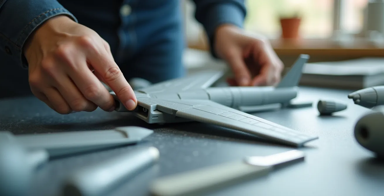
The first step in any diagnostic phase is effective inspection. Wing root gaps are a common affliction, but they are often invisible until the unforgiving weld of cement makes them permanent. Your mission is to make these potential flaws obvious. Relying on the naked eye under bright workshop lighting is a recipe for failure; subtle gaps and misalignments will be washed out by ambient light.
You must create conditions where the gaps reveal themselves. A simple and highly effective method is the backlight technique. By assembling the main components without glue and introducing a light source inside the dark fuselage cavity, you turn the model itself into a diagnostic tool. Even the finest hairline crack will glow, betraying its exact location and size. This allows for precise, pre-emptive correction rather than post-assembly guesswork.
This same principle applies to internal structures. Before closing up the fuselage, always test the fit of the cockpit tub, bulkheads, and any other interior parts. Place them inside one fuselage half, then fit the other half over them. Often, a seemingly perfect exterior fit is ruined by an internal part that is just a fraction of a millimeter too wide. Identifying this interference early is the key to avoiding a fuselage that refuses to close cleanly.
This proactive inspection transforms a potential disaster into a minor adjustment, setting the foundation for a flawless build.
Masking tape or Blue Tac: the best way to hold parts during a dry fit
Once you begin the diagnostic phase, you need reliable, non-permanent methods to hold assemblies together for inspection. The choice of holding method is not arbitrary; it depends on the parts being joined and the type of force required to simulate a glued seam. The two most common tools for this job, masking tape and poster tack (like Blue Tac), serve very different functions.
Masking tape is the workhorse for long, straight seams, such as joining fuselage halves or attaching wings. It provides a tensional force, pulling the two parts together along the length of the seam. This is crucial for evaluating a component’s structural integrity under the kind of stress a final bond would create. However, cheap or overly aggressive tape can lift delicate surface details or leave a residue, so quality is paramount.
Poster tack, by contrast, provides a compressive hold. It is best used for smaller, non-structural items like canopies, intakes, or ordnance. It pushes a part into place, making it ideal for checking the position and alignment of delicate components without applying risky tension. Its main drawback is the potential to leave an oily residue that can interfere with paint adhesion, so careful cleanup is essential. The following table breaks down the optimal use for each method.
Understanding these different holding methods allows you to select the right tool for the job. This table provides a quick reference for common dry-fitting scenarios.
| Method | Best For | Tension Type | Risk Level |
|---|---|---|---|
| Masking Tape | Long seams (fuselage) | Tensional force | May lift delicate details |
| Blue Tack | Canopies, small intakes | Compressive hold | Potential residue |
| Rubber Bands | Large assemblies | Strong continuous | Can deform soft plastic |
Choosing incorrectly can introduce stress or misalignment, invalidating your inspection and leading to false conclusions about the kit’s fit.
Checking wing angles: why eyes can deceive you and what jigs to use
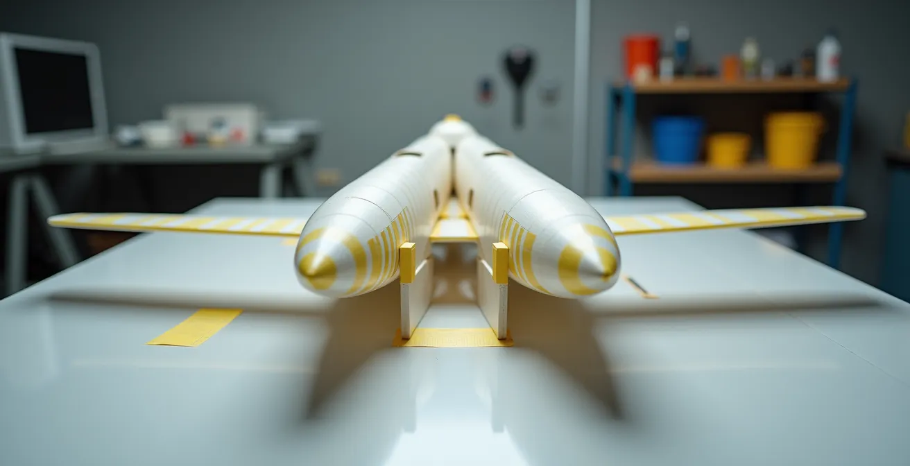
Human eyes are notoriously unreliable instruments for judging angles, especially the subtle dihedral (upward angle) or anhedral (downward angle) of aircraft wings. Perspective distortion, the angle of your head, and the lighting in the room can all conspire to make a perfectly straight wing look angled, or a correctly angled wing look flat. For critical alignments, you must trust instruments, not instincts.
Commercial wing alignment jigs are available, but a perfectly flat surface and a few simple tools are often sufficient. The goal is to remove perspective from the equation. One highly effective, if unconventional, method for verifying symmetry is to use a flatbed scanner or photocopier. By placing the taped-up model on the glass, you create a perfect two-dimensional image free from any distortion.
With this 2D scan, you can perform precise analysis:
- Overlay a digital grid to check for symmetry.
- Use software to measure the angles of the wings, tailplanes, and fins with pinpoint accuracy.
- Print the image and use a physical protractor to measure the angles against the kit’s specifications or historical reference documents.
This method provides objective, undeniable data about your assembly’s geometry. If a wing is drooping, you will know by exactly how many degrees. This allows for a calculated correction—such as shimming the wing root or bracing it during the gluing process—rather than a “best guess” eyeball adjustment that could make the problem worse.
Ultimately, a model with accurate, symmetrical wing angles will look correct from every viewpoint, a quality that can only be guaranteed through disciplined measurement.
Why cutting off the manufacturer’s locating pins often improves the fit?
Locating pins, the small plastic posts and corresponding holes found on parts like fuselage halves, are intended to aid alignment. In a perfect world, they would guarantee a flawless fit. We do not live in a perfect world. More often than not, these pins are a primary source of misalignment, and their removal is one of the most common and effective forms of pre-emptive correction.
The problem is one of manufacturing tolerances. The pins may be slightly too large for the holes, the holes slightly misdrilled, or minor mold-shift during production can throw them out of alignment by a fraction of a millimeter. When this happens, the pins prevent the two halves from seating properly, creating gaps and steps along the seam line. By forcing the parts together, you are introducing stress into the plastic, which can lead to warping or split seams later on. The pins become the problem, not the solution.
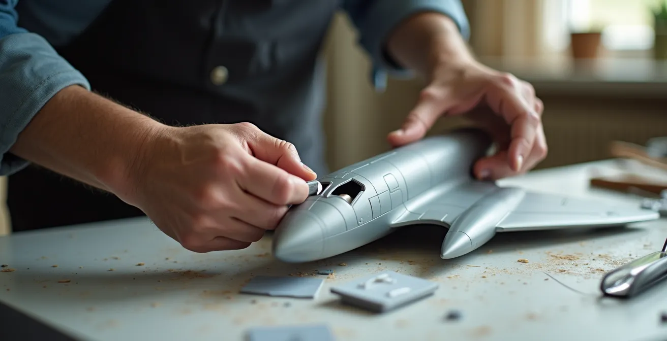
The professional approach is to treat locating pins with suspicion. During the initial dry fit, if the parts do not join perfectly, the pins are the first suspect. The solution is decisive: slice them off. With the pins removed, you can now manipulate the two halves to achieve a perfect flush fit along the entire seam. To maintain this alignment during gluing, you can add new, larger alignment tabs from scrap styrene sheet inside the fuselage. These provide a much larger contact area, ensuring a strong, perfectly aligned joint.
This principle is even true in the real world of aircraft manufacturing. It has always been a routine part of final assembly to deal with gaps at airframe joins. Mechanics work to make the outer skin surfaces flush and smooth, often dealing with parts fabricated at different sites that never fit together perfectly on the first try.
By removing these potential sources of error, you take full control of the alignment, relying on your skill rather than the factory’s occasionally flawed design.
How to trim internal tabs to close a stubborn fuselage gap?
Practice dry-fitting the parts at least two or three times before start squeezing the glue. If you miss this part, you will later have to perform some very hard filling, sanding and panel line rescribing sessions to remedy the problem.
– Scale Model Aircraft Expert Guide, Scale-Model-Aircraft.com Building Guide
Sometimes, a fuselage refuses to close even after the locating pins are removed. The cause is almost always hidden: an internal bulkhead, a cockpit tub, or an intake trunking part is interfering with the fit. The challenge is that you cannot see the point of contact. Shaving down plastic at random in the hope of finding the high spot is inefficient and destructive. You need a precise method to map the interference points.
The “contact point mapping” technique is a simple yet powerful diagnostic tool. By coloring the edge of the suspected internal part with a soft pencil or a dark, non-permanent marker, you create a transferable medium. When you test-fit the fuselage halves and press them together, the color will transfer from the internal part to the exact point on the inner fuselage wall where it is making contact. No more guesswork.
Once you separate the halves, the transferred markings will pinpoint the high spots with surgical precision. You can then use a sharp hobby blade to carefully shave or scrape away a small amount of plastic from these marked areas only. This targeted removal ensures that you are not removing material unnecessarily, which could compromise the part’s fit or structural integrity. A clean fit is achieved through systematic iteration, not brute force.
Your Action Plan: Pinpointing Internal Fit Issues
- Color the edge of internal part with dark pencil or dry-erase marker.
- Test-fit the part into fuselage – color transfers to exact interference points.
- Remove part and identify high spots from transferred markings.
- Use sharp #11 blade to precisely shave marked areas only.
- Repeat process until clean fit achieved without gaps.
By using this technique, you can solve even the most stubborn fit problems with minimal effort, ensuring that every internal component contributes to a perfect final assembly rather than obstructing it.
How to Organize Your Kit Assembly Sequence to Avoid Painting Disasters?
A successful build is not just about how the parts fit, but also the order in which you join them. The assembly sequence is your project blueprint. A poorly planned sequence can lead to “painting yourself into a corner,” where you can no longer access areas that need to be painted, such as cockpit interiors, wheel wells, or jet intakes. This is a planning failure, and it is entirely avoidable.
The key is to think in terms of subassemblies and assembly gates. A subassembly is a logical grouping of parts that can be built and painted as a separate unit before being added to the main model (e.g., the cockpit, the engine, the landing gear). An assembly gate is a point of no return—an irreversible step, like closing the fuselage halves or attaching the wings. Once you pass through a gate, you can’t go back.
Before you apply any glue, review the instruction sheet and create your own assembly flowchart. Identify every gate. For each subassembly, list all the parts that must be painted *before* it is installed and the gate is closed. According to a more efficient assembly line method, it’s best to work in these subassemblies; for instance, assemble the wings and, while they dry, prepare the fuselage. This creates a logical, efficient workflow and prevents disasters. Your checklist for this planning phase should include:
- Identify all irreversible assembly ‘gates’.
- List every part requiring paint before each gate.
- Create a visual flowchart of dependencies.
- Mark ‘Points of No Return’ where access becomes impossible.
- Dry-fit every subassembly before committing.
This strategic approach not only prevents painting errors but also makes the entire build process more organized and enjoyable, allowing you to focus on quality at each stage.
How to Align Fuselage Halves Perfectly When the Kit Is Warped?
Occasionally, you will encounter a kit where a major component, like a fuselage half, is warped right out of the box. This is a critical structural defect that must be rectified before any assembly can begin. A warped foundation guarantees a twisted and misaligned final structure. There are three common types of warpage: a bow (a curve along the length), a twist (like a propeller), or a flare (where the ends splay outwards).
The first step is diagnosis. Place the part on a known flat surface, like a piece of glass or a steel ruler, to identify the type and severity of the warp. The fix for warped plastic involves carefully controlled heat. The goal is to make the plastic pliable enough to be reshaped, but not so hot that it melts or loses detail. Boiling water is too hot and dangerous. The ideal temperature is between 140-160°F (60-70°C).
The process is systematic:
- Heat water to the target temperature.
- Immerse the warped section for 30 to 60 seconds until it becomes flexible.
- Remove the part and immediately hold or brace it in the corrected, straight position.
- Run it under cold water to “lock” the plastic in its new shape.
For more severe twists, this method can be combined with internal bracing. As noted by experts in publications like Model Aviation, the goal is to soften the structure enough to correct the warp, then let it cool in its new, correct shape. This is a powerful technique that can salvage a kit that might otherwise seem unusable.
By addressing these major defects at the very beginning, you ensure that the rest of your painstaking alignment work is built upon a solid and true foundation.
Key takeaways
- Dry-fitting is a non-negotiable diagnostic phase, not an optional step.
- Pre-emptive correction of fit issues is always more efficient than post-assembly remedial labor (filling and sanding).
- Trust instruments over instinct for critical alignments; your eyes will deceive you.
Thin vs Thick Cement: Which Glue Works Best for Joining Fuselage Halves?
The final act of joining major components is not about choosing the “strongest” glue; it’s about selecting the appropriate cement for the condition of the seam you’ve worked so hard to perfect. Your choice of adhesive is a direct consequence of your diagnostic work. Different cements are formulated for different gap conditions, and using the wrong one can undo all your careful preparation.
If your diagnostic and correction phase was successful, you will have a perfect, gap-free fit. For this ideal scenario, extra-thin liquid cement is the only correct choice. It is not applied before the parts are joined. Instead, the parts are held together tightly, and the watery cement is touched to the seam with a fine brush. Capillary action instantly wicks the cement deep into the join, creating a clean, strong weld from the inside out with absolutely no mess on the surface.
For a minor, hairline gap that you couldn’t fully eliminate (less than 0.5mm), a slightly thicker, medium-body cement is appropriate. This type has some minor gap-filling properties and is brushed onto the contact surfaces before they are joined. For any gap larger than this, you have not encountered a gluing problem; you have identified a failure in your diagnostic and correction phase. A detailed guide to professional techniques, like the two-step pro-welding method, can be found in a detailed guide on professional welding techniques, which emphasizes working in sequence and allowing each section to dry solidly.
The choice of cement is dictated by the quality of your fit. The following table outlines the correct tool for each job.
| Gap Condition | Cement Type | Application Method | Result |
|---|---|---|---|
| Perfect fit (no gap) | Extra-thin cement | Capillary flow along seam | Clean invisible weld |
| Small gap (0.1-0.5mm) | Medium cement | Brush application | Gap-filling with minimal cleanup |
| Larger gap (>0.5mm) | Thick cement/gap filler | Direct application | Structural fill requiring sanding |
Using cement as a structural filler is a sign of a failed process. The goal is a perfect weld on a perfect seam, a result only achievable through disciplined dry-fitting and correction.