The common advice to ‘just clamp it harder’ is why seams pop weeks later. A warped fuselage isn’t a glue problem; it’s a structural tension problem.
- The plastic has ‘memory’ and is constantly trying to revert to its warped shape, creating stress that breaks glue joints.
- The solution is to first release this stored energy with controlled heat, then build an internal skeleton to guarantee permanent alignment.
Recommendation: Stop fighting the warp. Instead, treat it like a car’s bent frame: diagnose the stress points, gently persuade the material back into shape, and then weld in structural reinforcements.
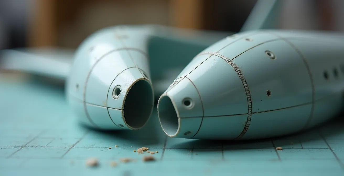
You open the box of a vintage kit, full of anticipation. Then you see it: the two fuselage halves form a distinct “banana” shape. The frustration is immediate. Every modeler has faced this, the result of an old mold or poor storage. The common wisdom is to reach for more clamps and stronger glue, trying to bully the parts into submission. But this is a battle of brute force you will always lose. The plastic is fighting back with a power you can’t see: stored energy.
This isn’t about a defective part; it’s a problem of structural engineering. The plastic has a ‘memory’ of its warped shape, and it will exert a slow, relentless pressure to return to it. Forcing it together with clamps is a temporary fix that leads to seams popping open days or weeks after you thought the job was done. A true craftsman, like a panel beater straightening a car’s chassis, doesn’t just hammer a dent out. They understand the metal’s tension, applying precise force and heat to release the stress and restore the original form.
This guide adopts that master’s mindset. We are going to stop fighting the warp and start re-engineering the fuselage from the inside out. We will explore how to persuade the plastic to forget its warped memory using controlled heat. We will learn to diagnose the true source of misalignment—which isn’t always where you think it is. Finally, we will build an internal skeleton that provides permanent structural integrity, ensuring your seams are not just filled, but are truly gone forever.
This article provides a structured approach to transform that warped plastic from a source of frustration into a demonstration of skill. Below is a summary of the key stages we will cover to master this process.
Summary: A Structural Guide to Warped Fuselages
- The Hot Water Bath: How to Unbend Plastic Memory Without Melting Details?
- Why Do Long Fuselage Parts Warp in the Box and How to Store Them?
- Pressure Points: Knowing When to Use Strong Clamps and When to Use Tape?
- Why Seams Pop Open a Week After Gluing Warped Parts (and How to Reinforce)?
- How to Glue Sprue Tabs Inside the Fuselage to Force Alignment?
- Why Dry-Fitting Every Part Saves You Hours of Filling and Sanding Later?
- Thin vs Thick Cement: Which Glue Works Best for Joining Fuselage Halves?
- How to Eliminate Fuselage Seams So They Disappear Under a Coat of Silver Paint?
The Hot Water Bath: How to Unbend Plastic Memory Without Melting Details?
The first tool in our frame-straightening arsenal is heat, but this requires finesse, not brute force. The goal isn’t to melt the plastic, but to make it pliable enough to forget its warped shape. This happens at a specific scientific threshold. The scientific basis for this treatment shows that polystyrene, the common plastic in model kits, reaches its glass transition at around 100°C (212°F). At this temperature, the material softens significantly. Our goal is to work just below this point, making the plastic suggestible without turning it into soup and erasing fine panel lines.
The process is about controlled persuasion. You must first mechanically constrain the part in its *correct* shape. This can be done with a simple jig, weights on a flat surface, or by taping it to a known-straight edge. Only then do you introduce heat. This forces the plastic’s molecular structure to realign while it is being held in the desired position. Cooling it down while it’s still constrained locks this new, correct shape into its memory.
To do this safely and effectively, follow a precise workflow:
- Heat water to a target range of 175-195°F (79-91°C). This is hot enough to be effective but safely below the temperature where details are lost. Use a thermometer.
- Test the temperature first. Immerse a piece of sprue from the same kit for 30 seconds. If it becomes overly soft or shows any surface damage, your water is too hot.
- Constrain the part. Before it touches the water, ensure the warped piece is firmly held in its corrected alignment.
- Immerse the constrained part. A good rule of thumb is about 3 minutes of immersion for every 1/8 inch (3mm) of plastic thickness.
- Cool completely while constrained. Immediately run the part under cold water or let it air cool for at least 15 minutes, all while it remains in the jig. Releasing it too soon will allow the old warp to return.
This method doesn’t just bend plastic; it performs a factory reset on its structural memory, giving you a neutral, stress-free component to work with.
Why Do Long Fuselage Parts Warp in the Box and How to Store Them?
Understanding why a fuselage warps is the first step in preventing it. The primary culprit is not a single hot day, but temperature fluctuations. Plastic expands when heated and contracts when cooled. Over months or years, cycles of temperature change in a storage space like an attic or garage introduce stress into the long, unsupported fuselage parts. This cumulative stress eventually causes the plastic to permanently deform, or warp. The parts are literally pulling themselves out of shape over time.
A case study from a modeling forum illustrates this perfectly. A modeler stored kits in an attic for just one year, where temperatures varied widely. Upon retrieving them, decals were ruined, and at least one kit had significantly warped parts. In stark contrast, kits stored inside a house cupboard for several years, where the temperature was stable, remained in perfect condition. This proves that stability is more important than a specific temperature. A constant 75°F (24°C) is far better than a range that swings from 50°F to 100°F (10°C to 38°C).

The ideal storage environment, as shown above, is one that mimics the conditions inside your home: cool, dry, and above all, stable. Avoid attics, garages, and sheds at all costs. Store kits flat to prevent gravity from contributing to the problem, and never stack so many that the bottom boxes are crushed. You are not just storing plastic; you are preserving the engineered precision of the kit. A little environmental control goes a long way in preventing hours of corrective work later.
By treating your unbuilt kits with the same care you give your finished models, you are already winning the fight against warped parts.
Pressure Points: Knowing When to Use Strong Clamps and When to Use Tape?
Once you have a warped part, the instinct is to force it into alignment. But applying pressure is a matter of finesse, not force. The tools you use—tape, rubber bands, or clamps—are not interchangeable. Each applies a different type of pressure, and using the wrong one can cause more damage than it solves. Strong clamps apply high point pressure, which is excellent for forcing a corrected part against an internal brace but can easily crack thin plastic or obliterate surface detail if used on an unsupported area.
Tape, on the other hand, provides a gentle, distributed pressure. It’s your primary tool for diagnosis and initial alignment. It holds parts together without stress, allowing you to see where the natural tension and gaps are. Think of it as a set of helping hands, not a vise. Your pressure strategy should be sequential: diagnose with tape, then apply strong force only where it is absolutely necessary and fully supported from within.
This comparative analysis shows that each method has a specific role in your workshop. As detailed in an alignment guide for large scale models, the key is choosing the right tool for the job.
| Method | Best Use Case | Pressure Type | Risk Level |
|---|---|---|---|
| Masking Tape | Initial alignment diagnosis | Gentle, distributed | Low – safe for details |
| Rubber Bands | Long-term storage alignment | Moderate, distributed | Low – but can break over time |
| Strong Clamps | Forcing warped areas against internal braces | High point pressure | High – can damage thin parts |
| Shrink Wrap | Full hull storage | Even, complete coverage | Medium – can cause twisting over years |
Action Plan: Your Sequential Pressure Strategy
- Initial Diagnosis: Start with a tape-only dry fit to identify natural stress points and gaps without applying any force.
- Mapping High Spots: Use a pencil to mark the “high spots” where the parts bow out and don’t align naturally. These are your primary targets for correction.
- Sectional Work: Apply tape as temporary ‘hinges’ on one end of the fuselage, allowing you to work on one section at a time.
- Strategic Clamping: Use strong clamps only where internal reinforcement (like a bulkhead or spar) provides solid backing support. This directs the force effectively.
- Detail Preservation: Never place a clamp directly over raised surface details, clear canopies, or thin-edged parts. Always protect the surface.
By using pressure as a surgical tool rather than a blunt instrument, you maintain control and protect the delicate integrity of the kit.
Why Seams Pop Open a Week After Gluing Warped Parts (and How to Reinforce)?
You’ve done it. The warped fuselage is clamped and glued, the seam looks perfect. A week later, a hairline crack appears. This frustrating phenomenon isn’t a sign of bad glue; it’s a victory for plastic memory. As expert modeler Mike Poole of the Austin Scale Modeler’s Society explains, the material itself is the culprit. In his guide, he states:
The plastic has ‘memory’ and is constantly trying to return to its warped shape. This slow, persistent force is what breaks the glue joint, not a ‘bad glue job’.
– Mike Poole, Austin Scale Modeler’s Society – Straightening Warped Plastic Without Drama
A simple glue joint, even a strong solvent weld, is just a thin line of defense against this constant, invisible tension. To win this war, you can’t just glue the edges; you must build an internal chassis that mechanically holds the fuselage in the correct shape. This internal skeleton actively counteracts the plastic’s memory, distributing the stress away from the fragile seam line.
This internal structure doesn’t have to be complex. It can be built from simple plastic card and sprue. The key is strategic placement. A central “keel” running the length of the fuselage provides longitudinal rigidity, while perpendicular “bulkheads” at key stress points maintain the correct cross-sectional shape. This internal framework acts like the steel frame of a building, providing all the structural integrity and leaving the outer seam as nothing more than a cosmetic surface.
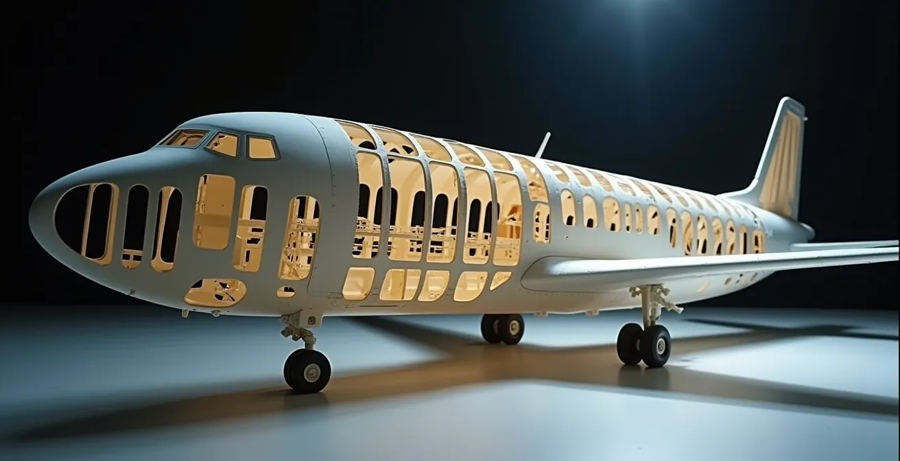
These reinforcements turn a flexible, weak shell into a rigid, monolithic structure. The most effective technique is to use slightly oversized bulkheads that actively push the fuselage halves into the correct shape from the inside. This pre-loads the structure, ensuring that even if the plastic tries to revert, it has nowhere to go. Each reinforcing piece should be allowed to cure fully before the fuselage halves are joined, creating a powerful and permanent internal tensioning system.
By building this internal frame, you are no longer just gluing plastic; you are engineering a solution that guarantees the warp will never return.
How to Glue Sprue Tabs Inside the Fuselage to Force Alignment?
The most effective internal reinforcements are those that use leverage to their advantage. Simply gluing a flat piece of plastic card inside isn’t enough. You need to create structural elements, and the most accessible material for this is the kit’s own sprue. By cutting tabs from the sprue and gluing them as cross-braces or bulkheads, you create a powerful internal tensioning system. The key to their strength, however, lies in a two-stage curing process.
Never try to glue a brace to both fuselage halves at once. The uncured joints will flex, and the brace will simply conform to the warp. Instead, you must create a solid anchor point first. Glue the brace or bulkhead securely to *one* fuselage half and let it cure completely, for at least 24 hours. Test it; it should be rock solid. This piece is now an immovable part of that fuselage half. Now, when you apply fresh glue and join the halves, this pre-cured brace acts as a powerful lever, forcing the second, flexible half into alignment against it.
This method turns simple sprue into an engineered component. A professional builder working on large fuselages noted that their primary method for stability involves bonding a full-length keel and perpendicular bulkheads to one half first. This creates a rigid “chassis” that dictates the final shape, making the assembly of the second half a simple matter of mating it to a perfectly aligned structure. The principle is the same: build a strong frame on one side, then attach the other side to it.
- Stage 1: The Anchor. Glue your sprue tab or plastic card bulkhead to ONE fuselage half only. Use enough cement to create a strong weld.
- Full Cure. Let this single joint cure for 24-48 hours. It must be completely rigid and unyielding before you proceed.
- Stage 2: The Union. Apply fresh glue to the exposed edge of the now-cured brace and to the contact area on the opposing fuselage half.
- Join and Clamp. Bring the halves together. The solid brace will resist the warp and force the entire assembly into the correct alignment as the new joint cures.
You are using the inherent strength of a cured joint to overcome the weakness of an uncured one, creating a structure that is stronger than the original parts.
Why Dry-Fitting Every Part Saves You Hours of Filling and Sanding Later?
Dry-fitting is the single most important diagnostic tool in modeling, yet it is often rushed or misunderstood. It’s not just about seeing if two fuselage halves meet. A true diagnostic dry-fit, or a “skeletal dry-fit,” involves assembling *all* the internal components—cockpit tub, bulkheads, wing spars, landing gear bays—and taping them together without a single drop of glue. This reveals the true source of a warp, which is often not the fuselage itself.
A classic case study from a modeler demonstrates this perfectly. He was struggling with a badly warped fuselage, assuming the kit’s main parts were flawed. However, a full skeletal dry-fit revealed the true culprit: the cockpit tub was slightly oversized. It was pushing the fuselage halves apart from the inside, creating the warp. By identifying this, he was able to sand the cockpit part down for a perfect fit *before* any gluing. This saved him what would have been hours of filling and sanding a phantom seam caused by internal pressure.
This process is your blueprint. It allows you to map out all the stress points and interference issues. Use strips of paper as feeler gauges to measure the precise size of gaps. Use a pencil to mark high spots that need sanding. Create a simple jig from foam board or Lego bricks to hold the entire skeleton in perfect alignment while you test each part. This turns a simple check into a full engineering analysis, allowing you to solve problems at their root cause.
Checklist: The Complete Diagnostic Dry-Fit
- Mark High Spots: During dry-fitting, use a soft pencil to lightly mark any areas on the joining surfaces that sit proud and create gaps.
- Measure Gaps: Use thin strips of paper as feeler gauges to measure the exact width of any gaps, helping you decide between filling or bracing.
- Test All Internals: Never test just the fuselage halves. Always fit the cockpit, bulkheads, and wing spars simultaneously to check for internal pressure.
- Use a Jig: Create a simple jig from foam board or scrap wood to hold the main components in their correct alignment throughout the diagnostic process.
- Document Problems: Take photos of problem areas with your phone before disassembly. This provides a crucial reference when you start making modifications.
By treating dry-fitting as a diagnostic phase, you shift from reacting to problems to preventing them entirely.
Thin vs Thick Cement: Which Glue Works Best for Joining Fuselage Halves?
Choosing the right adhesive is not about finding the “strongest” glue; it’s about selecting the right tool for a specific task in the assembly sequence. For joining fuselage halves, especially warped ones, a multi-stage approach using different types of cement yields a far superior result. Relying on a single type of glue for the entire process is inefficient and often leads to weaker joints or cosmetic flaws.
Professional modelers often use a three-part strategy. First, thick tube cement is used to tack the fuselage halves together at a few key, high-stress points. Its slow curing time and gap-filling properties allow you to make minor alignment adjustments, while its initial tack provides immediate holding power. Once this is set, the real work begins. Extra-thin solvent cement is then applied along the entire seam. This cement works by capillary action, flowing deep into the tightest gaps and chemically welding the plastic together on a molecular level. This process creates a perfectly fused joint.
Finally, for installing internal braces where instant, rigid strength is needed, CA glue (super glue) with an accelerator is the ideal choice. It creates an immediate bond, allowing you to build your internal skeleton quickly and without waiting for solvent to cure. Understanding the role of each cement type is crucial for a strong, clean build, as this comparative guide to model adhesives highlights.
| Cement Type | Working Time | Best Application | Capillary Action |
|---|---|---|---|
| Extra-thin (Tamiya) | 5-10 seconds | Perfect-fit seams | Excellent – flows into gaps |
| Medium viscosity | 30-60 seconds | Standard assembly | Moderate |
| Thick tube cement | 2-3 minutes | Gap filling, initial tacking | None – stays in place |
| Sprue Goo (DIY) | 1-2 minutes | Structural gaps | None – fills voids |
By using each glue for its intended purpose, you are not just sticking parts together; you are executing a precise chemical welding and structural bonding plan.
Key Takeaways
- A warped part is storing energy. Your first job is to release that energy with controlled heat, not fight it with force.
- True alignment comes from within. An internal skeleton of braces and bulkheads provides permanent structural integrity that a simple glue seam cannot.
- Dry-fitting is not a simple check; it’s a full diagnostic assembly of the model’s ‘skeleton’ to find the root cause of misalignment before any glue is applied.
How to Eliminate Fuselage Seams So They Disappear Under a Coat of Silver Paint?
A silver paint finish is the ultimate test of your bodywork. It is notoriously unforgiving and will reveal every single scratch, ghost seam, and surface flaw. Achieving an invisible seam under silver is the final proof that your structural work was successful. This is a cosmetic process built on a foundation of solid engineering; as the experts at Scale Model Aircraft Magazine state, “A perfect, invisible seam under silver paint is impossible without strong internal bracing. The bracing prevents ‘ghost seams’ from reappearing weeks later due to stress.”
The technique begins with the gluing process itself. When applying extra-thin cement to the seam, firmly squeeze the two fuselage halves together. This forces a small, raised bead of melted plastic to ooze out along the join line. This bead is your best friend. Do not touch it. Let it cure for a full 24 to 48 hours until it is rock-hard. This bead is now solid plastic, effectively one piece with the fuselage.
Next, use the back edge (not the sharp cutting edge) of a hobby knife blade to scrape this bead down until it is nearly flush with the surrounding surface. This removes the bulk of the material without gouging the plastic. Follow this with a progressive sanding regimen, starting with a medium grit (e.g., 400) and working your way up to a very fine, polishing grit (e.g., 2000 or higher). The final, crucial test is to apply a gloss black primer coat. Black is even more revealing than silver and will instantly show any remaining flaws. Address these minor imperfections, and only then are you ready for the final silver coat.
By following this meticulous process of welding, scraping, sanding, and testing, you ensure the seam is not just filled, but has truly and permanently vanished, leaving behind nothing but a perfect, uninterrupted surface.